
Methods and systems for reducing noise in optoelectronic oscillators

a technology of optoelectronic oscillators and noise reduction, which is applied in the direction of radio-over-fiber, electrical equipment, fiber transmission, etc., can solve the problems of reducing the overall spectral purity of the source, reducing the phase noise of the conventional architecture, etc., and achieves the reduction of inherent fiber noise, reducing the noise of the optoelectronic oscillator, and increasing the fiber-optic path length

Active Publication Date: 2018-02-06
RAYTHEON CO
View PDF5 Cites 19 Cited by
  • Summary
  • Abstract
  • Description
  • Claims
  • Application Information

AI Technical Summary

Benefits of technology

This patent is about systems and methods for reducing noise in optoelectronic oscillators. One example involves a double pass configuration, which cancels out noise through active or passive approaches. Other components like amplifiers, modulators, phase shifters, and optical filters can be added to further reduce noise and increase the fiber-optic path length while maintaining low phase noise. Another embodiment involves using a retro-reflector with a phase conjugate mirror to cancel out the frequency range of inherent fiber noise. The method also involves receiving the optical signal and a reference signal, and transmitting a control signal to an optical component to cancel out the frequency range of inherent fiber noise in the retro-reflected optical signal. Overall, this patent provides technical means to reduce noise in optoelectronic oscillators and improve their performance.

Problems solved by technology

Unfortunately, conventional architectures still suffer from some phase noise, which reduces the overall spectral purity of the source.

Method used


Image

  • Methods and systems for reducing noise in optoelectronic oscillators
  • Methods and systems for reducing noise in optoelectronic oscillators
  • Methods and systems for reducing noise in optoelectronic oscillators

Examples


Embodiment Construction

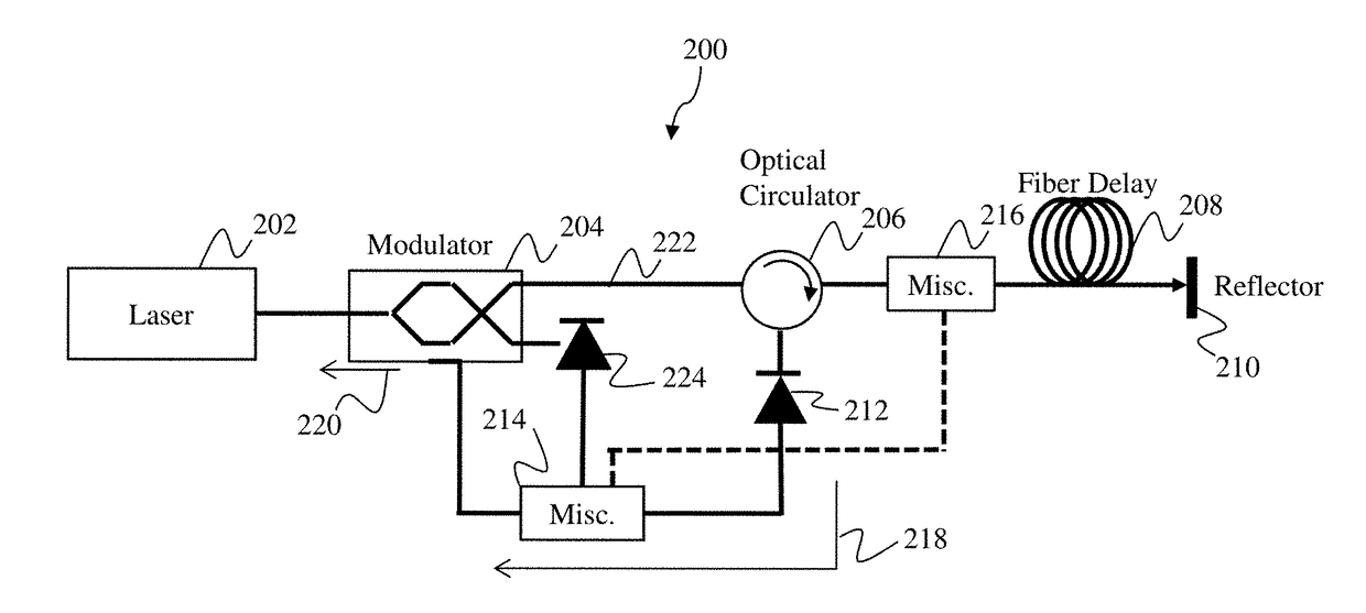
[0021]Aspects and embodiments are directed to an approach for reducing phase noise in optoelectronic oscillators. Certain examples involve the implementation of a double pass configuration optoelectronic oscillator system, which may include optical circulators, retro-reflectors, couplers, or other similarly functioning elements, positioned within a fiber-optic path of the system. These examples allow for inherent fiber noise cancellation through active, or passive, approaches. Additional components and devices, such as amplifiers, modulators, phase shifters, and optical filters, may be included to further reduce inherent fiber noise (and / or environmentally induced noise) and allow an increased fiber-optic path length, with a low close-in phase noise.

[0022]Oscillators with a high stability timing and low close-in phase noise are desired for numerous applications. Several devices and systems have been proposed for generating a reference oscillator with these characteristics. One such ...


PUM


Abstract

Optoelectronic oscillator systems and an optoelectronic oscillator noise reduction method. One example of an optoelectronic oscillator system includes an optical source positioned at a first end of a fiber-optic path, the optical source being configured to transmit an optical signal along the fiber-optic path, an optical modulator positioned to receive and modulate the optical signal based on at least a reference signal, a retro-reflector positioned at a second end of the fiber-optic path, the retro-reflector being configured to receive and retro-reflect the optical signal, the retro-reflected optical signal having at least a frequency range of inherent fiber noise canceled, and an optical circulator positioned along the fiber-optic path between the optical modulator and the retro-reflector, the optical circulator being configured to direct the optical signal to the retro-reflector and direct the retro-reflected optical signal along a feedback path to a first photodetector to generate the reference signal.

Description

RELATED APPLICATIONS[0001]This application claims priority under 35 U.S.C. § 119(e) to U.S. Provisional Application Ser. No. 62 / 103,691, titled “METHODS AND APPARATUS FOR REDUCING NOISE IN OPTOELECTRONIC OSCILLATORS,” filed on Jan. 15, 2015, which is hereby incorporated herein by reference in its entirety.BACKGROUND[0002]Optoelectronic oscillators (OEOs) are high-frequency radio frequency (RF) sources with very low phase noise. Unfortunately, conventional architectures still suffer from some phase noise, which reduces the overall spectral purity of the source. The two basic sources of noise in optoelectronic oscillators include fiber dependent amplitude noise from Rayleigh and Brilloin scattering, which is converted to phase noise during photo-detection processes, and phase noise induced from environmental conditions. Several and ongoing attempts have been made to eliminate these sources of noise in optoelectronic oscillators. These include, for example, optical and electronic filte...

Claims


Application Information

Patent Timeline
Patent Type & Authority Patents(United States)
IPC IPC(8): H04B10/50H04B10/00H04B10/2575H04B1/00
CPCH04B10/5057H04B1/00H04B10/2575H04B10/00H04B2210/006H04B10/50572
Inventor KOWALEVICZ, ANDREW
Owner RAYTHEON CO
Learn More