
Inventory management system

a management system and inventory technology, applied in the field of inventory management systems, can solve the problems of inability to guarantee the accuracy of inventory over time, human error, and the cost of more secure automated ways of dispensing or delivering one item at a time in a secure automated manner, and achieve the effect of convenient and easy recording of take/return, enhancing the use of button modules, and ensuring accuracy

Active Publication Date: 2018-02-06
CUBEX LLC
View PDF8 Cites 1 Cited by
  • Summary
  • Abstract
  • Description
  • Claims
  • Application Information

AI Technical Summary

Benefits of technology

[0007]Each button module comprises a housing with typically two buttons, e.g., one a “Take” button and the other a “Return” button, inside each button module is a wireless transmitter and battery, and the pushing of either the Take or the Return button generates a wireless signal indicating that action, together with an ID, unique to that button module. The wireless base station receiving these one-way signals from multiple button modules arrayed throughout the storage area, is connected to the computer that is maintaining the perpetual inventory, and using that unique ID which has been previously associated with the particular item stored at that location (a process known as “assignment”), the computer can adjust the inventory up or down for that item, one increment for each button push. This solves the convenience issue for a single user taking / returning multiple items. Once logged into the system, that user can walk around the stock room and simply record that they removed or replaced items by pushing the take / return buttons a corresponding number of times, maintaining an accurate record of inventory in the data base. This is preferable to having to note down what was taken / returned at each location and returning to the computer screen to enter that data after the fact.
[0008]Even requiring a user to push a button a number of times to indicate the exact number of items taken or returned, cannot be guaranteed to be accurate over time. It is prone at best to human error, or to laziness, or at worst, a deliberate attempt to take items without recording that action. However more secure automated ways of dispensing or delivering one item at a time in a secure automated manner is orders of magnitude more expensive. Consequently many inventory systems rely on the human operator to honestly and accurately manually record what they have done. The objective of the button module is to make the recording of the Take / Return as convenient, easy and error free as possible.
[0009]The objective of the invention is to augment the use of the button module to allow multiple simultaneous users and to increase the case of use of supervisory functions
[0010]One of the issues with that button module method as described so far, is that the identification of the user performing the take / return action is based on that user logging into the computer system. This means that only one user can be active at a time. In that circumstance the current versions of the button modules cannot distinguish between users. This is a serious restriction in a large warehouse where you would want many users operating simultaneously. One of the purposes of this invention is to solve this issue by identifying the user when they activate the button. This is achieved by having, e.g., a Near Field Communication (NFC) chip in each button module that is activated by the user's mobile device, either a cell phone or tablet computer, and receive the identity of that activating device. When the user subsequently presses a button, the button module is able to also transmit that user's identification back to the computer along with the item ID and the quantity taken / returned, allowing the central computer to distinguish between the actions of multiple users.
[0011]While much of the activity in a warehouse is having users take and return items, there are also supervisory functions that need to be performed. Included in these activities are assigning and de-assigning items to a location and its associated button module, determining the Maximum fill level (also known as the “Par” level) and Minimum level (also known as the re-order point) and Emergency low level (also known as Critical level). Also for performing the function of taking physical inventory and entering actual inventory levels which, over time, may not be what is reflected in the computer database due to users who might not have always recorded accurately the quantity they had taken / returned. In order to achieve these supervisory functions, the user may use a mobile device that gives them access, either through a Wi-Fi or a cellular connection, to the database for the many items in the warehouse. At each inventory location the user has to accurately look up and identify the database item corresponding to the item they are dealing with. Consequently another purpose of this invention is to establish that connection between the item location and the correct item in the database, automatically. The user establishes a connection between their NFC enabled mobile device, whether it be a cell phone or tablet, and the NFC chip in the button module, by placing the mobile device in close proximity to the button module, typically by tapping the device on the button module. This allows the mobile device to access information about that unique location in the master database enabling the supervisor to assign / de-assign items, modify the maximum or minimum re-order levels, and perform and enter physical inventory counts and other adjustments.

Problems solved by technology

Even requiring a user to push a button a number of times to indicate the exact number of items taken or returned, cannot be guaranteed to be accurate over time.
It is prone at best to human error, or to laziness, or at worst, a deliberate attempt to take items without recording that action.
However more secure automated ways of dispensing or delivering one item at a time in a secure automated manner is orders of magnitude more expensive.

Method used


Image

  • Inventory management system
  • Inventory management system
  • Inventory management system

Examples


Embodiment Construction

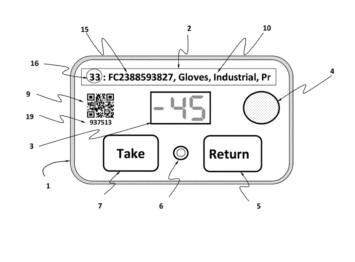
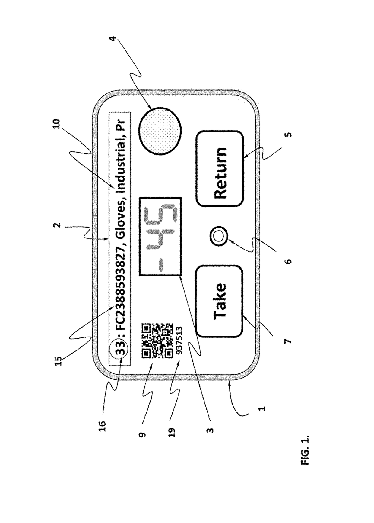
[0018]FIG. 1 shows an example of the elements of the front of a button module. It comprises a housing 1, which may be affixed, secured, attached, or otherwise positioned at any number of locations. On the front of the button module are one or more buttons, typically a Take 7 and a Return 5 button. There may also be affixed a label 2 that contains the item description 10, and usually the item ID 15 (e.g., inventory number) of the item that has been assigned at that location, and optionally, a unique short number 16 assigned by the computer when the label is printed, that is associated in the database to the unique (and unchanging) ID 19 of the button module itself, which number is part of the wireless transmission from the button module. This unique short number 16 can be used as a reference to the item and its location, when the user is looking up information in a user interface, and can be used to retrieve and enter information about that item, with a very quick 2 or 3 digit entry,...


PUM


Abstract

An inventory management system for managing multiple inventory items by multiple users is described and generally includes one or more button modules each having at least a first button and a second button and an NFC chip incorporated into the button module. Each NFC chip has a predetermined and unique module identification signal associated with the button module. The button module may further include a circuitry unit configured to receive a predetermined and unique mobile device identification signal from a mobile device for combination with the module identification signal from the NFC chip. The circuitry unit may receive a count signal indicative of an increase or decrease in inventory count corresponding to the first button or the second button being depressed upon the button module and combine the count signal with the mobile device identification signal and module identification signal for transmission to a remote server.

Description

CROSS-REFERENCE TO RELATED APPLICATIONS[0001]This application claims the benefit of priority to U.S. Provisional Application No. 62 / 218,301 filed Sep. 14, 2015, which is incorporated herein by reference in its entirety.FIELD OF THE INVENTION[0002]The present invention relates to inventory management systems used to track the quantity of items taken or replaced from the inventory. More specifically, the present invention relates to inventory manage systems which can be used w wirelessly record multiple inventory items using one or more button modules.BACKGROUND OF THE INVENTION[0003]The computer management of perpetual inventory is a common process today. There are many methods for tracking who takes, returns or restocks items in a store room or warehouse in order to maintain a record of the on-hand quantity, and to monitor that quantity in order to place orders to replenish stock. A typical system comprises a computer with a database storing information about each item, and means fo...

Claims


Application Information

Patent Timeline
Patent Type & Authority Patents(United States)
IPC IPC(8): G06F17/00G06Q10/08G06K7/10G06K7/14
CPCG06K7/10297G06Q10/087G06K7/1417
Inventor HIGHAM, JOHN D.VISSER, ANTON
Owner CUBEX LLC
Learn More