Fluid filter with thermal control and pressure bypass

a technology of fluid filter and thermal control, which is applied in the direction of filtration separation, membrane technology, separation processes, etc., can solve the problems of affecting the affecting the cooling efficiency of the system, so as to protect the efficacy of the system, relieve undesirable excess pressure, and improve the cooling efficiency

Active Publication Date: 2018-02-06
PARKER INTANGIBLES LLC
View PDF7 Cites 0 Cited by
  • Summary
  • Abstract
  • Description
  • Claims
  • Application Information

AI Technical Summary

Benefits of technology

[0010]The filter assembly is suitable for incorporation into a refrigeration system, air conditioning system, or other suitable cooling system. The filter assembly combines a thermally responsive control of fluid flow with a pressure bypass relief. Through the capability of the filter valve to operate in the cold and hot modes, the configuration of the filter assembly particularly ensures communication of fluid of suitable cooling temperature through a cooling system to enhance the cooling efficiency. The filter assembly further protects the efficacy of the system by operating the filter valve in a pressure bypass mode to relieve undesirable excess pressure. The filter valve, therefore, provides for enhanced cooling efficiency and efficacy of operation as compared to conventional filter devices.

Problems solved by technology

As the filter is used, contaminants may be build up within the filter media, which impedes or restricts the fluid flow.
With the flow restricted, undesirable pressure may build up within the filter and clog the filter, which can result in damage to the system in which the filter is incorporated.
Coolant fluid that flows through refrigeration systems, air conditioning systems, and similar cooling systems including a heat exchanger presents particular issues with respect to fluid flow through a filter assembly.
Accordingly, the temperature of the coolant fluid at the filter assembly is significant, but control of fluid flow through the filter assembly based on temperature has not been adequately addressed by conventional filter assemblies.

Method used


Image

  • Fluid filter with thermal control and pressure bypass
  • Fluid filter with thermal control and pressure bypass
  • Fluid filter with thermal control and pressure bypass

Examples


Embodiment Construction

[0017]Embodiments of the present invention will now be described with reference to the drawings, wherein like reference numerals are used to refer to like elements throughout. It will be understood that the figures are not necessarily to scale.

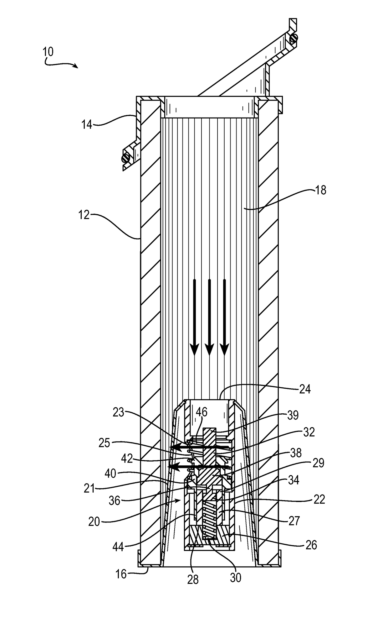
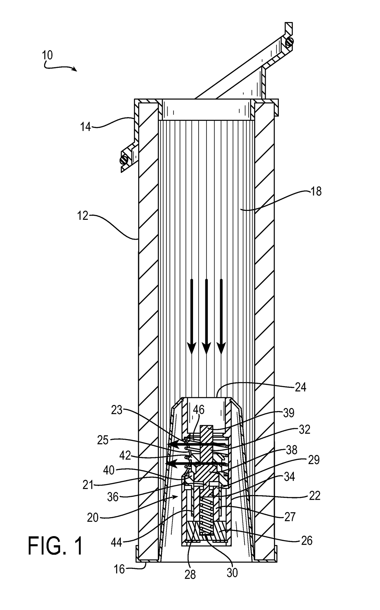
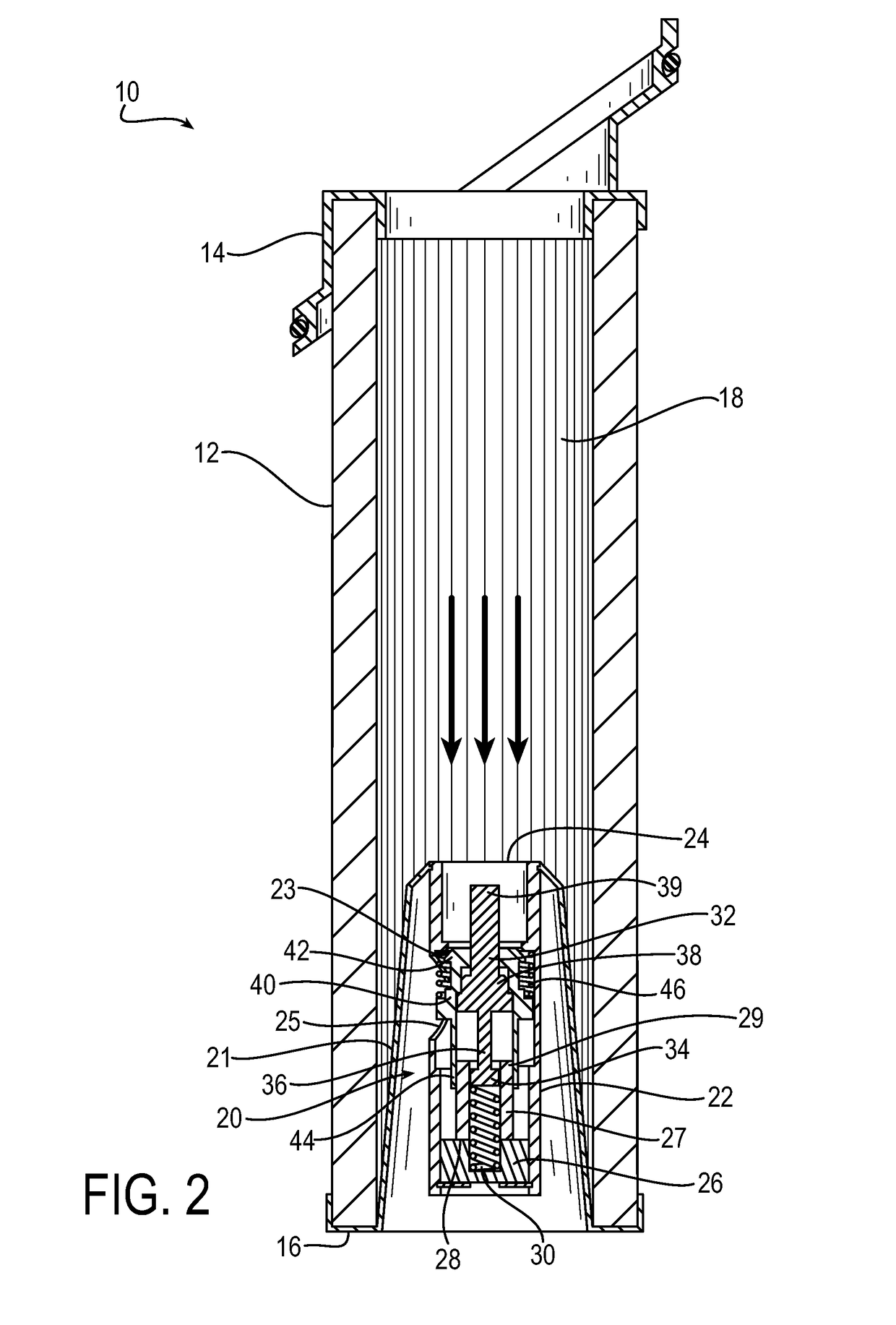
[0018]As further detailed below, an aspect of the invention is a filter assembly that includes a filter media for filtering a fluid, and a filter valve having a fluid inlet and a fluid outlet for controlling a flow of the fluid through the filter assembly. The valve operates by providing thermal based control of the fluid flow through the filter assembly, in combination with pressure bypass relief. In exemplary embodiments, filter valve includes a thermally active element (e.g., a thermally active wax element) that changes shape between a first configuration and a second configuration in response to a temperature variation. When the thermally active element is in the first configuration, the valve is open with the fluid inlet in fluid communic...


PUM

PropertyMeasurementUnit
temperatureaaaaaaaaaa
pressureaaaaaaaaaa

Abstract

A filter assembly includes a filter media for filtering a fluid, and a valve having a fluid inlet and a fluid outlet for controlling a flow of the fluid through the filter assembly. The valve includes a thermally active element that changes shape between a first configuration and a second configuration in response to a temperature variation. When the thermally active element is in the first configuration the valve is open with the fluid inlet in fluid communication with the fluid outlet, and the thermally active element changes shape to the second configuration to close the valve. The thermally active element may move a valve poppet against a valve seat to close the valve. A pressure bypass is configured to open the valve in response to a pressure increase in the filter assembly above a threshold pressure when the thermally active element is in the second configuration.

Description

RELATED APPLICATIONS[0001]This application claims the benefit of U.S. Provisional Application No. 61 / 885,546 filed Oct. 2, 2013, which is hereby incorporated herein by reference.FIELD OF INVENTION[0002]The present invention relates generally to fluid filter assemblies, and more particularly to valve assemblies that control fluid flow through such fluid filter assemblies.BACKGROUND OF THE INVENTION[0003]A variety of applications employ fluid filter assemblies. Such applications include, for example, hydraulic systems, fuel delivery systems, coolant systems, and engine lubrication systems. Filter assemblies may be used to filter any type of fluid, such as, for example, gasoline, diesel fuel, lubricating oil, water, coolant fluid, and others. For example, a filter assembly may filter out contamination from a coolant fluid that flows from a cooler tank and ultimately through a heat exchanger as part of a refrigeration system, air conditioning system, or other suitable cooling system as ...

Claims


Application Information

Patent Timeline
Patent Type & Authority Patents(United States)
IPC IPC(8): B01D35/02B01D35/147B01D29/23B01D29/60
CPCB01D35/147B01D29/232B01D2201/291B01D29/608
Inventor TROTT, JOHNSANATGAR, HOMAYOUN
Owner PARKER INTANGIBLES LLC
Why Eureka
Try Eureka