Organic light emitting diode display

a light-emitting diode and organic technology, applied in the direction of basic electric elements, electrical equipment, semiconductor devices, etc., can solve the problems of poor deposition of common electrodes, deterioration of etc., to improve the display quality and reliability of products, improve the film quality of common electrodes, and reduce manufacturing costs

Active Publication Date: 2018-01-30
SAMSUNG DISPLAY CO LTD
View PDF17 Cites 1 Cited by
  • Summary
  • Abstract
  • Description
  • Claims
  • Application Information

AI Technical Summary

Benefits of technology

[0010]Aspects of embodiments of the described technology are directed toward an organic light emitting diode display capable of preventing (or protecting from) deterioration of an emission characteristic of an emission layer and / or of enhancing display quality and reliability of products by preventing (or protecting) a non-deposition area from being generated in a common electrode when the common electrode is formed by a spin deposition method (spin deposition).
[0015]According to the exemplary embodiment, it is possible to reduce manufacturing costs by forming the common electrode by spin deposition and improve film quality of the common electrode by preventing an abnormal area (a portion which is less deposited or not deposited) from being generated in the common electrode. Therefore, it is possible to improve display quality and reliability of products by preventing damage to the emission layer due to the filler.

Problems solved by technology

However, as the substrate is enlarged, the deposition of the common electrode is not performed well due to the thickness of the pixel defining layer outside the substrate.
Since the damage region of the emission layer is widely enlarged over time, display quality and reliability of products deteriorate.

Method used


Image

  • Organic light emitting diode display
  • Organic light emitting diode display
  • Organic light emitting diode display

Examples


Embodiment Construction

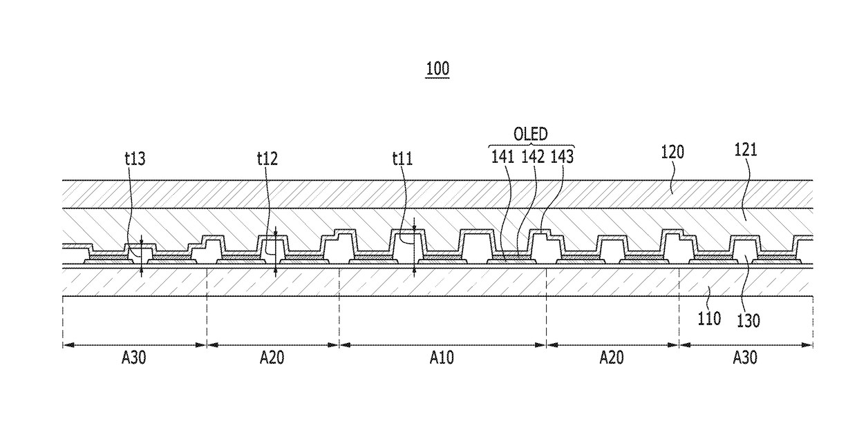
[0026]The present disclosure will be described more fully hereinafter with reference to the accompanying drawings, in which exemplary embodiments of the disclosure are shown. As those skilled in the art would realize, the described embodiments may be modified in various different ways, all without departing from the spirit or scope of the present disclosure.

[0027]It will be understood that when an element such as a layer, film, region, or substrate is referred to as being “on” another element, it can be directly on the other element or intervening elements may also be present. Further, in the specification, the word “on” refers to positioning on or below the object portion, and does not essentially mean positioning on the upper side of the object portion based on a gravity direction.

[0028]In addition, unless explicitly described to the contrary, the word “comprise” and variations such as “comprises” or “comprising”, will be understood to refer to the inclusion of stated elements but...


PUM


Abstract

An organic light emitting diode display including: a plurality of pixel electrodes formed in a display area of a substrate; a pixel defining layer having an opening exposing a part of each of the plurality of pixel electrodes and formed in the display area; a plurality of emission layers formed on the plurality of pixel electrodes; and a common electrode formed on the pixel defining layer and the plurality of emission layers. The pixel defining layer is formed with a smaller thickness farther from the center of the display area.

Description

CROSS-REFERENCE TO RELATED APPLICATION[0001]This application claims priority to and the benefit of Korean Patent Application No. 10-2015-0027322, filed in the Korean Intellectual Property Office on Feb. 26, 2015, the entire content of which is incorporated herein by reference.BACKGROUND[0002]1. Field[0003]The described technology relates generally to an organic light emitting diode display, and more particularly, to an organic light emitting diode display for enhancing film quality of a common electrode.[0004]2. Description of the Related Art[0005]An organic light emitting diode display includes an organic light emitting diode configured by an emission layer, an anode injecting holes to the emission layer, and a cathode injecting electrons to the emission layer. The electrons and the holes are coupled with each other in the emission layer to generate excitons, and light is emitted by energy generated when the excitons fall from an excited state to a ground state.[0006]Any one of the...

Claims


Application Information

Patent Timeline
Patent Type & Authority Patents(United States)
IPC IPC(8): H01L51/00H01L51/56H01L27/32H01L51/52
CPCH01L51/0021H01L51/56H01L27/3246H01L51/5221H10K59/122H10K71/60H10K50/82H10K2102/351H10K71/00
Inventor KOO, YONG-KYOUNG
Owner SAMSUNG DISPLAY CO LTD
Why Eureka
Try Eureka