Scroll compressor

a compressor and scroll technology, applied in the direction of mechanical control devices, instruments, liquid fuel engines, etc., can solve the problems of excessive wear of scroll components and reduce the efficiency of the compressor, and achieve the effects of increasing the flexibility of the design of the movable scroll counterweight, increasing the stability and durability of operation, and a larger area

Active Publication Date: 2018-01-30
EMERSON CLIMATE TECH (SUZHOU) CO LTD
View PDF20 Cites 0 Cited by
  • Summary
  • Abstract
  • Description
  • Claims
  • Application Information

AI Technical Summary

Benefits of technology

[0074]In a scroll compressor according to an embodiment of the present application, a space for rotation of the movable scroll counterweight may be formed between the main bearing housing and the thrust plate. In other words, there is only a need for simple modification to the main bearing housing, or there is no need for modification to the main bearing housing (for example, the volume of the movable scroll counterweight is set to be suitable for rotation of the movable scroll counterweight in the existing space of the main bearing housing). Thus, the movable scroll counterweight may simply be configured. In addition, the main bearing housing and the thrust plate may be integrally formed, or may be formed as separate components and then be fixed together by a fastening device. With these constructions, the flexibility of the design of the movable scroll counterweight increases. In addition, in the case that the main bearing housing and the thrust plate are separate components, the thrust plate may be designed appropriately such as to provide the movable scroll with a thrust surface having a greater area, so as to increase the stability and durability of the operation of the scroll compressor.
[0075]In a scroll compressor according to an embodiment of the present application, at least one oil supply groove is provided on an inner circumference of the cylindrical portion of the movable scroll counterweight. Lubricant can be easily and reliably supplied onto the thrust surfaces between the end plate of the movable scroll and the thrust plate through the oil supply groove, so as to achieve a better lubrication. In addition, the portion of the cylindrical portion in which the oil supply groove is provided may be higher than the other portions of the cylindrical portion, or the portion of the cylindrical portion in which the oil supply groove is provided can be constructed to be adjacent to a lower surface of the end plate of the movable scroll, thereby facilitating the supply of lubricant to the thrust surface of the movable scroll with ease. Further, a step portion may be formed at the bottom wall of the movable scroll counterweight. A ratio of the lubricant flowing upwardly through the oil supply grooves to the lubricant flowing downwardly through the driving hole formed in the bottom wall can be controlled by using the step portion, so as to realize a reasonable supply of the lubricant to various parts that need be lubricated.

Problems solved by technology

Therefore, when the scroll compressor 100 is operated at a low rotational speed, the radial seal force Fflank between the fixed scroll 150 and the movable scroll 160 may be insufficient, thereby resulting in a reduced efficiency of the compressor, whereas when the scroll compressor 100 is operated at a high rotational speed, the radial seal force Fflank between the fixed scroll 150 and the movable scroll 160 may be excessively large, thereby causing an excessive wear of the scroll components.

Method used


Image

  • Scroll compressor
  • Scroll compressor
  • Scroll compressor

Examples


Embodiment Construction

[0099]The following description of preferred embodiments is only exemplary, and is never a limitation to the present application and its application or usage.

[0100]An identical reference numeral is adopted to represent an identical component throughout the accompanying drawings. Therefore, the constructions of the same components will no longer be repeated in this description.

[0101]The basic structure and principle of a scroll compressor 10 according to the first embodiment of the application will be described below with reference to FIG. 3-13.

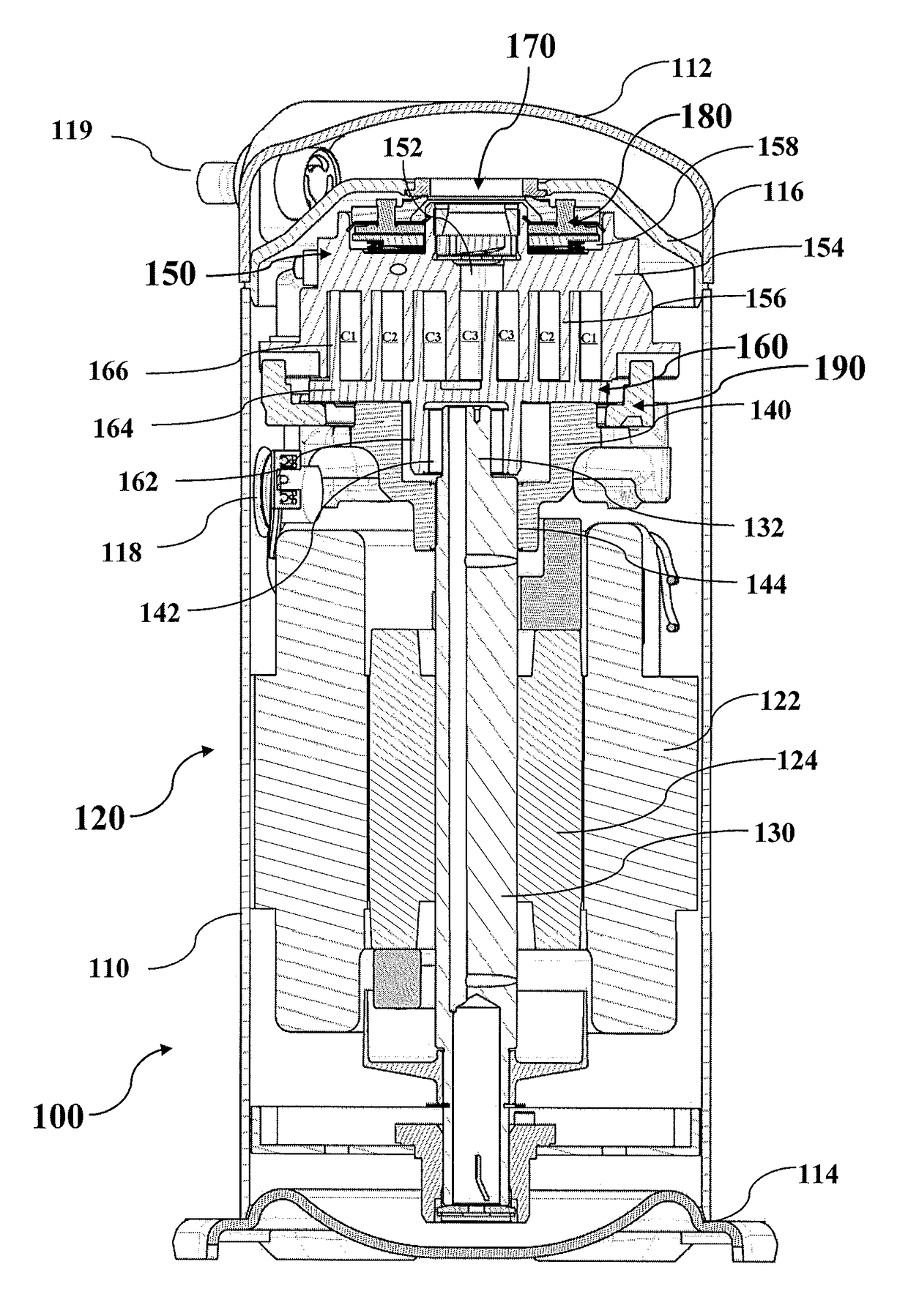
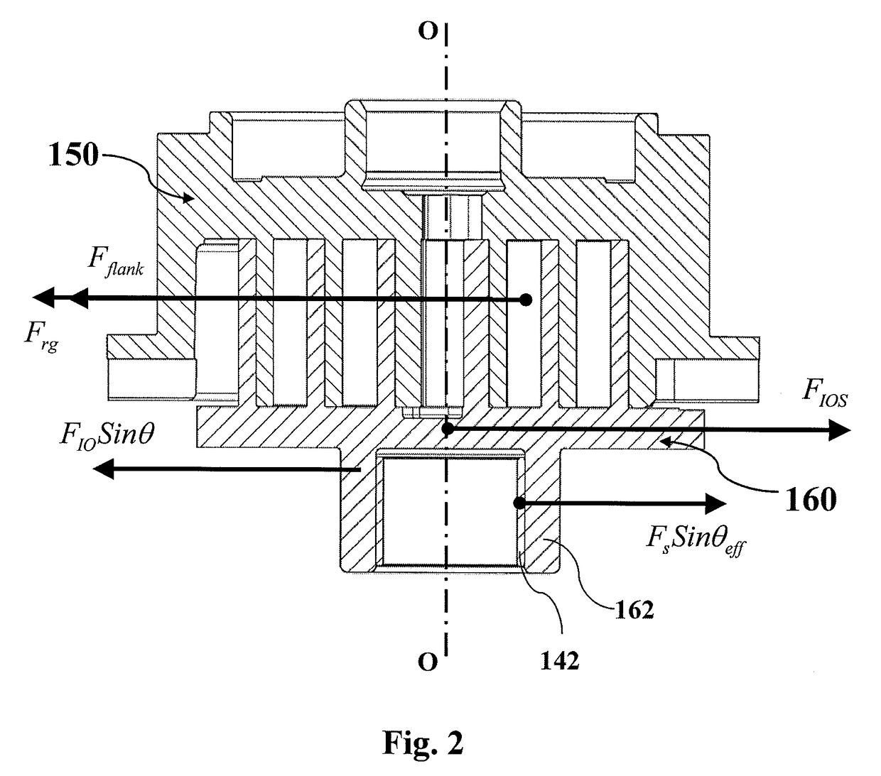
[0102]As shown in FIG. 3, the scroll compressor 10 according to an embodiment of the present application generally includes a housing 110, a top cover 112 arranged at one end of the housing 110, a bottom cover 114 arranged on the other end of the housing 110, and a partition plate 116 arranged between the top cover 112 and the housing 110 to divide an inner space of the compressor into a high-pressure side and a low-pressure side. The high-pre...


PUM


Abstract

A scroll compressor (10), comprising a fixed scroll (150), a movable scroll (160) and a drive shaft (30); the scroll compressor (10) further comprises a movable scroll counterweight (40); the movable scroll counterweight (40) is configured to rotate with the drive shaft (30); and the centrifugal force of the movable scroll counterweight (40) caused by the rotation acts on the hub (162) of the movable scroll (160). The above structure can effectively reduce the impact of the centrifugal force of the movable scroll on the radial seal of a scroll component, thus achieving proper radial sealing force between the fixed scroll and the movable scroll at any rotating speed.

Description

CROSS REFERENCE OF RELEVANT APPLICATION[0001]This application is the national phase of International Application No. PCT / CN2013 / 073917, titled “SCROLL COMPRESSOR”, filed on Apr. 9, 2013, which claims priority to the Chinese patent application No. 201210105213.1 titled “scroll compressor” and filed with the Chinese Patent Office on Apr. 11, 2012, to the Chinese patent application No. 201220151455.X titled “scroll compressor” and filed with the Chinese Patent Office on Apr. 11, 2012, to the Chinese patent application No. 201310045737.0 titled “scroll compressor” and filed with the Chinese Patent Office on Feb. 5, 2013, and to the Chinese patent application No. 201320067054.0 titled “scroll compressor” and filed with the Chinese Patent Office on Feb. 5, 2013, the disclosures of which are incorporated herein by reference in their entireties.FIELD[0002]The present application relates to a scroll compressor.BACKGROUND[0003]The descriptions in this section merely provide background informa...

Claims


Application Information

Patent Timeline
Patent Type & Authority Patents(United States)
IPC IPC(8): F16F15/32F01C1/063F03C2/02F01C1/02G05G1/00F04C2/02F04C29/02F04C18/02F04C23/00F04C29/00
CPCF04C18/0215F04C23/008F04C29/023F04C29/0021F04C2240/807F04C2240/50
Inventor SU, XIAOGENGGUO, WEIHUASUN, QINGFENGHU, ZHEN
Owner EMERSON CLIMATE TECH (SUZHOU) CO LTD
Why Eureka
Try Eureka