Ink jet printing apparatus and ink jet printing method
a printing apparatus and ink jet technology, applied in printing and other directions, can solve the problems of induction noise, deviation of ink landing position and transfer error of printing data, deterioration of image quality, etc., and achieve the effect of minimizing image defects
- Summary
- Abstract
- Description
- Claims
- Application Information
AI Technical Summary
Benefits of technology
Problems solved by technology
Method used
Image

Examples
first embodiment
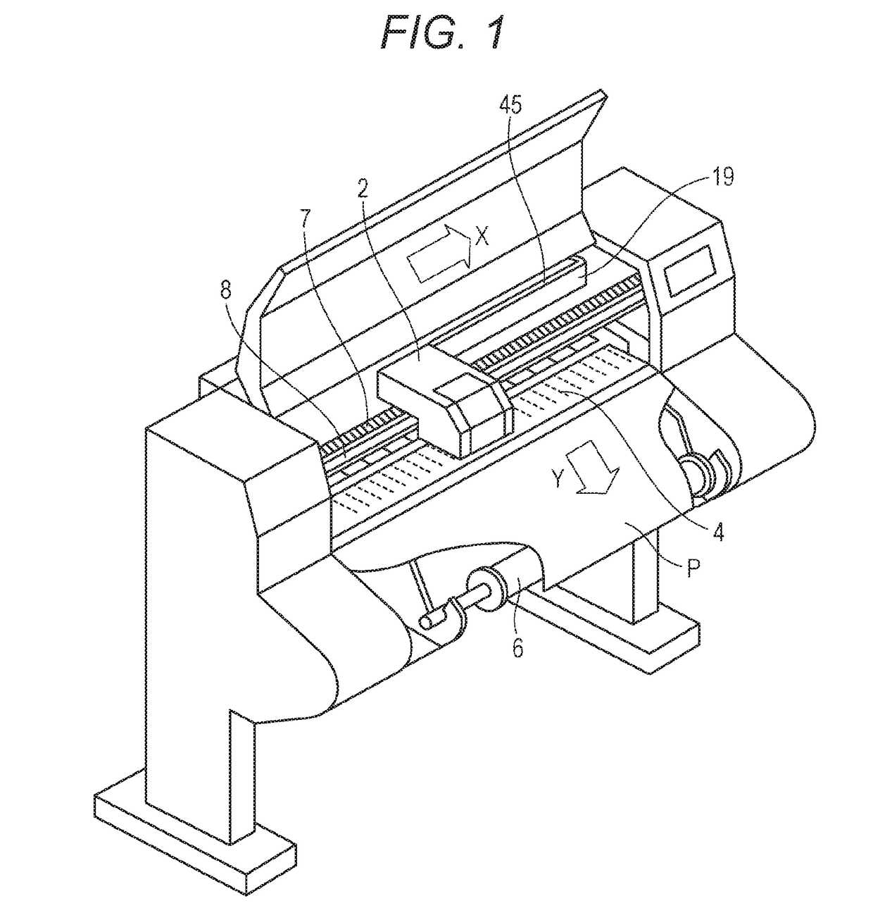
[0030]FIG. 1 illustrates an external appearance of an ink jet printing apparatus according to the embodiment (hereinafter also referred as printer). The printer is a so-called serial scanning printer that prints an image by scanning a printing head in a crossing direction (X direction) perpendicular to the conveyance direction (Y direction) of a printing medium P.
[0031]The configuration and the operation of the ink jet printing apparatus will schematically be described using FIG. 1. A printing medium P is conveyed in Y direction on a spool 6 supporting the printing medium P by a conveyance roller that is driven by a conveyance motor (not shown) via a gear. Meanwhile, a carriage unit 2 is swept, at a predetermined conveyance position, along a guide shaft 8 extending in X direction by a carriage motor (not shown). In this scanning step, an ejection operation is performed at an ejection port of a printing head (described later) detachable to the carriage unit 2 at a timing based on a p...
second embodiment
[0104]In the first embodiment, as described above, the processing of tentatively determining a driving pulse is performed such that a driving pulse corresponding to the ink temperature is selected according to the predetermined driving pulse table in which a plurality of driving pulses is specified.
[0105]In contrast, in the embodiment described below, the processing of tentatively determining a driving pulse is performed such that a reference driving pulse corresponding to the ink temperature is selected, and then pulse widths of the reference driving pulse is modulated according to conditions.
[0106]The description on the portion similar to the first embodiment will be omitted.
[0107]FIG. 12 is a flow chart illustrating a processing procedure of tentatively determining a driving pulse in the embodiment.
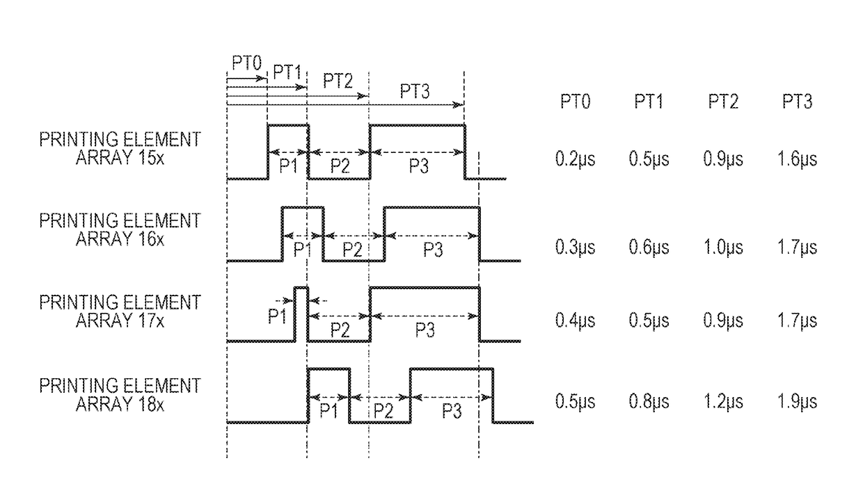
[0108]When the processing of tentatively determining a driving pulse starts in Step S10 illustrated in FIG. 10, the reference driving pulse for each printing element array is determine...
third embodiment
[0123]In the first and second embodiments, the driving pulse previously stored in the ROM 102 is used when the maximum overlapped level of invert timing is higher than a predetermined threshold.
[0124]In the embodiment, in contrast, when the maximum overlapped level of invert timing is higher than a predetermined threshold and the driving pulse that has been tentatively determined at a preceding timing is set as a driving pulse to be actually applied, the actually applied driving pulse is used again.
[0125]The description on the portion similar to the first and second embodiments will be omitted.
[0126]FIG. 15 is a flow chart for explaining the driving pulse control of the embodiment.
[0127]For the embodiment also, the driving pulse control illustrated in FIG. 15 is performed every 5 ms during printing an image. The time interval of performing the driving pulse control is not limited to 5 ms and can suitably be set to different time interval.
[0128]The process from Steps S20 to S24 in FI...
PUM
 Abstract
Description
Claims
Application Information
 - R&D
- Intellectual Property
- Life Sciences
- Materials
- Tech Scout
- Unparalleled Data Quality
- Higher Quality Content
- 60% Fewer Hallucinations
Browse by: Latest US Patents, China's latest patents, Technical Efficacy Thesaurus, Application Domain, Technology Topic, Popular Technical Reports.
© 2025 PatSnap. All rights reserved.Legal|Privacy policy|Modern Slavery Act Transparency Statement|Sitemap|About US| Contact US: help@patsnap.com