
High gradient permanent magnet elements for charged particle beamlines

a permanent magnet element and beamline technology, applied in the field of charged particle beam focusing, can solve the problems of reducing the focusing strength of conventional quads, complex construction, and large amount of magnetic materials, and achieve the effect of high 2n-pole field uniformity, simple structure, and low cos

Active Publication Date: 2018-01-16
EUCLID TECHLABS LLC
View PDF11 Cites 2 Cited by
  • Summary
  • Abstract
  • Description
  • Claims
  • Application Information

AI Technical Summary

Benefits of technology

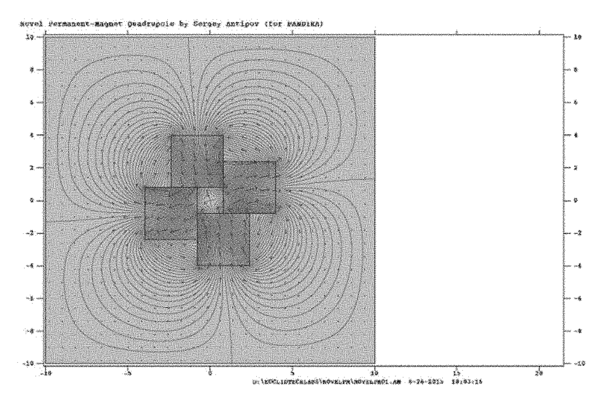
The present invention provides a technique for constructing compact, high gradient magnetic lenses for charged particle beam focusing. The invention provides methods for adjusting the focusing strength of the lenses, based on thermal control, mechanical motion of the magnetic chips within the yoke. The invention offers a simple, efficient, and inexpensive apparatus to focus and correct aberrations in charged particle beams using permanent magnets inserted into a supporting structure which also holds the configuration of the magnets. The use of a novel configuration of permanent magnet slabs allows for a more compact device with high focusing strength compared to conventional permanent magnet focusing elements. The invention also includes methods for tuning or stabilizing the magnetic fields, such as thermal control, addition of ferromagnetic shims, using a piezoelectric actuator or other linear motor to deform the support structure, using an adjustable iris, adjusting the axial (longitudinal) offset of the focusing device with respect to the other elements in a beamline, or any combination of these methods.

Problems solved by technology

The use of PMs eliminates the need for a current source to generate the magnetic field but can be inconvenient in terms of adjusting the magnetic field and hence the focusing properties of the lens on the fly.
Halbach quads require a relatively large amount of magnetic material, are complex to construct, and typically achieve a lower focusing strength than conventional quads.

Method used


Image

  • High gradient permanent magnet elements for charged particle beamlines
  • High gradient permanent magnet elements for charged particle beamlines
  • High gradient permanent magnet elements for charged particle beamlines

Examples


Embodiment Construction

[0022]The best mode for carrying out the invention is presented in terms of its preferred embodiment, herein depicted within the Figures. It should be understood that the legal scope of the description is defined by the words of the claims set forth at the end of this patent and that the detailed description is to be construed as exemplary only and does not describe every possible embodiment since describing every possible embodiment would be impractical, if not impossible. Numerous alternative embodiments could be implemented, using either current technology or technology developed after the filing date of this patent, which would still fall within the scope of the claims.

[0023]It should also be understood that, unless a term is expressly defined in this patent there is no intent to limit the meaning of that term, either expressly or by implication, beyond its plain or ordinary meaning, and such term should not be interpreted to be limited in scope based on any statement made in an...


PUM

PropertyMeasurementUnit
sizeaaaaaaaaaa
magnetic fieldaaaaaaaaaa
temperatureaaaaaaaaaa

Abstract

The present invention provides a technique for constructing compact, high gradient magnetic lenses for charged particle beam focusing. Methods for adjusting the focusing strength of the lenses are provided, based on thermal control, mechanical motion of the magnetic chips within the yoke. The present invention is a method for designing and fabricating permanent magnet focusing elements that are compact, simple to construct, and having a large, adjustable focusing strength. Applications include beamlines for THz radiation sources, free electron lasers, wakefield accelerators and any other charged particle devices that require a compact beamline.

Description

RELATED APPLICATIONS[0001]There present application claims benefit of U.S. Provisional Application 62 / 299,459 filed on Feb. 24, 2016 and incorporated by reference as if fully rewritten herein.BACKGROUND OF THE INVENTIONTechnical Field of the Invention[0002]The present invention is in the technical field of charged particle beam focusing, and in particular relates to compact permanent magnet based focusing and correction lenses capable of achieving high focusing strengths. The invention provides the means to develop beamlines for advanced rf sources and also for the control of beam instabilities in novel particle accelerators.Description of the Related Art[0003]Permanent magnets (PMs) in beam focusing devices have been in use for a number of years. The use of PMs eliminates the need for a current source to generate the magnetic field but can be inconvenient in terms of adjusting the magnetic field and hence the focusing properties of the lens on the fly. The most commonly used PM qua...

Claims


Application Information

Patent Timeline
Patent Type & Authority Patents(United States)
IPC IPC(8): H01J37/14H01F7/02H01J1/50H01J37/26
CPCH01J1/50H01F7/0284H01F7/0221H05H7/04H05H2007/043H01J3/24
Inventor ANTIPOV, SERGEYLI, YINGJEJING, CHUNUANGKOSTIN, ROMANQIU, JIAQUWANG, DANSCHOESSOW, PAUL
Owner EUCLID TECHLABS LLC
Learn More