
Power storage apparatus and method of operating power storage apparatus

a technology of power storage and power storage equipment, which is applied in the direction of electrical equipment, cell temperature control, cell components, etc., can solve the problems of excessive rise in temperature of exhaustion of heat from the inside of the container to the outside, etc., and achieves the effect of suppressing the influence of the outside air, improving the thermal insulation property of the container, and not increasing the operation cost and maintenance cos

Active Publication Date: 2018-01-02
NGK INSULATORS LTD
View PDF25 Cites 1 Cited by
  • Summary
  • Abstract
  • Description
  • Claims
  • Application Information

AI Technical Summary

Benefits of technology

The present invention maintains the temperature of an electric cell chamber without increasing operation and maintenance costs. It achieves this by using an air flow to exhaust heat from the chamber and improves the thermal insulation of the container. The invention also prevents excessive heat from escaping to the battery chamber and suppresses the influence of outside air. Additionally, the invention ensures that the exhaust capacity of heat from the chamber is maintained even when the temperature of outside air is high.

Problems solved by technology

However, as mentioned in Paragraph 0010 of Patent Document 1, it is not preferable that the temperature of the inside of the container excessively rises, and therefore heat is exhausted from the inside of the container to the outside as necessary.

Method used


Image

  • Power storage apparatus and method of operating power storage apparatus
  • Power storage apparatus and method of operating power storage apparatus
  • Power storage apparatus and method of operating power storage apparatus

Examples


Embodiment Construction

[0050](Components of Power Storage Apparatus)

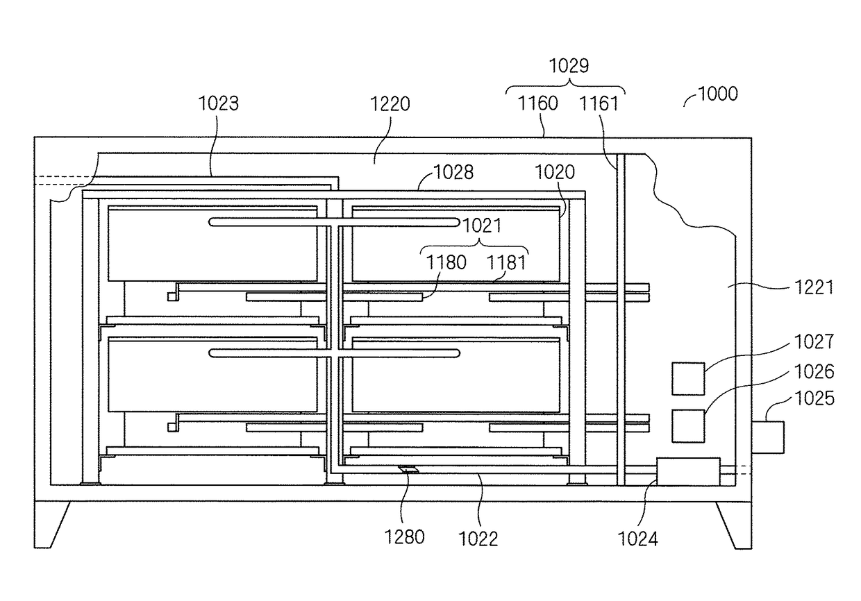
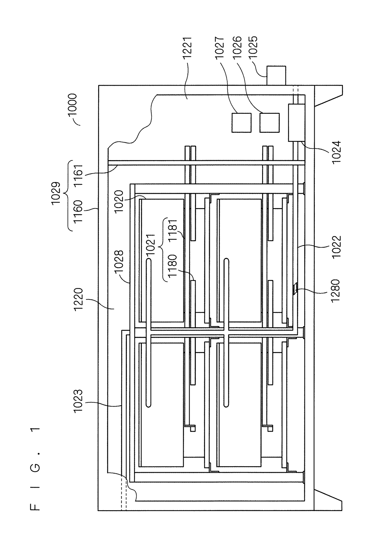
[0051]Schematic diagrams in FIG. 1 and FIG. 2 show a preferred embodiment of a power storage apparatus. FIG. 1 is a front view. FIG. 2 is a rear view. Schematic diagrams in FIG. 3 and FIG. 4 show a module battery. FIG. 3 is a perspective view. FIG. 4 is a sectional view. A block diagram in FIG. 5 shows a controller, and the like. The power storage apparatus stores power in a sodium-sulfur battery (NaS battery). The power storage apparatus is preferably connected to an electric power system, and used for the adjustment of power supply / demand, prevention of power failure, and the like.

[0052]As shown in FIG. 1 and FIG. 2, a power storage apparatus 1000 includes module batteries 1020, bus bars 1021 outside the module batteries, an intake pipe 1022, an exhaust pipe 1023, a blower 1024, an external temperature sensor 1025, an accessory 1026, a controller 1027, a battery stand 1028, and a sealed container 1029.

[0053]The sealed container 1029 inc...


PUM


Abstract

A battery chamber is formed inside a sealed container. A module battery and a charging / discharging path outside a battery are housed in the battery chamber. In the module battery, an electric cell chamber and an air chamber are formed inside a heat-insulating container. The electric cell chamber and the air chamber are divided by a heat transfer wall. An electric cell of a sodium-sulfur battery, and a charging / discharging path inside a battery are housed in the electric cell chamber. An intake path starts from outside of the sealed container and leads to the air chamber. An exhaust path starts from the air chamber and leads to the sealed container. The blower generates an air flow that sequentially flows through the intake path, the air chamber and the exhaust path. In a case where the cooling of the electric cell chamber is required, the air flow is generated.

Description

TECHNICAL FIELD[0001]The present invention relates to a power storage apparatus and a method of operating a power storage apparatus.BACKGROUND ART[0002]A sodium-sulfur battery (NaS battery) operates at a high temperature. Therefore, in the NaS battery, electric cells, a heater, and the like are housed inside a container (heat-insulating container), and the temperature of the inside of the container is maintained at a high temperature, as shown in Patent Document 1. However, as mentioned in Paragraph 0010 of Patent Document 1, it is not preferable that the temperature of the inside of the container excessively rises, and therefore heat is exhausted from the inside of the container to the outside as necessary.[0003]On the other hand, in a power storage apparatus (power storage compensation apparatus) provided with a NaS battery, a battery (module battery) in which electric cells are housed inside a container is sometimes further housed in an unsealed container (package), as shown in P...

Claims


Application Information

Patent Timeline
IPC IPC(8): H01M10/39H01M10/63H01M2/10H01M10/627H01M10/6563H01M10/655H01M10/48H01M10/613H01M50/204H01M50/253
CPCH01M10/3909H01M10/613H01M10/655H01M10/486H01M10/6563H01M2/1088H01M10/627H01M50/253H01M10/658H01M50/204Y02E60/10
Inventor TAMAKOSHI, TOMIOHATTA, TETSUYA
Owner NGK INSULATORS LTD
Learn More