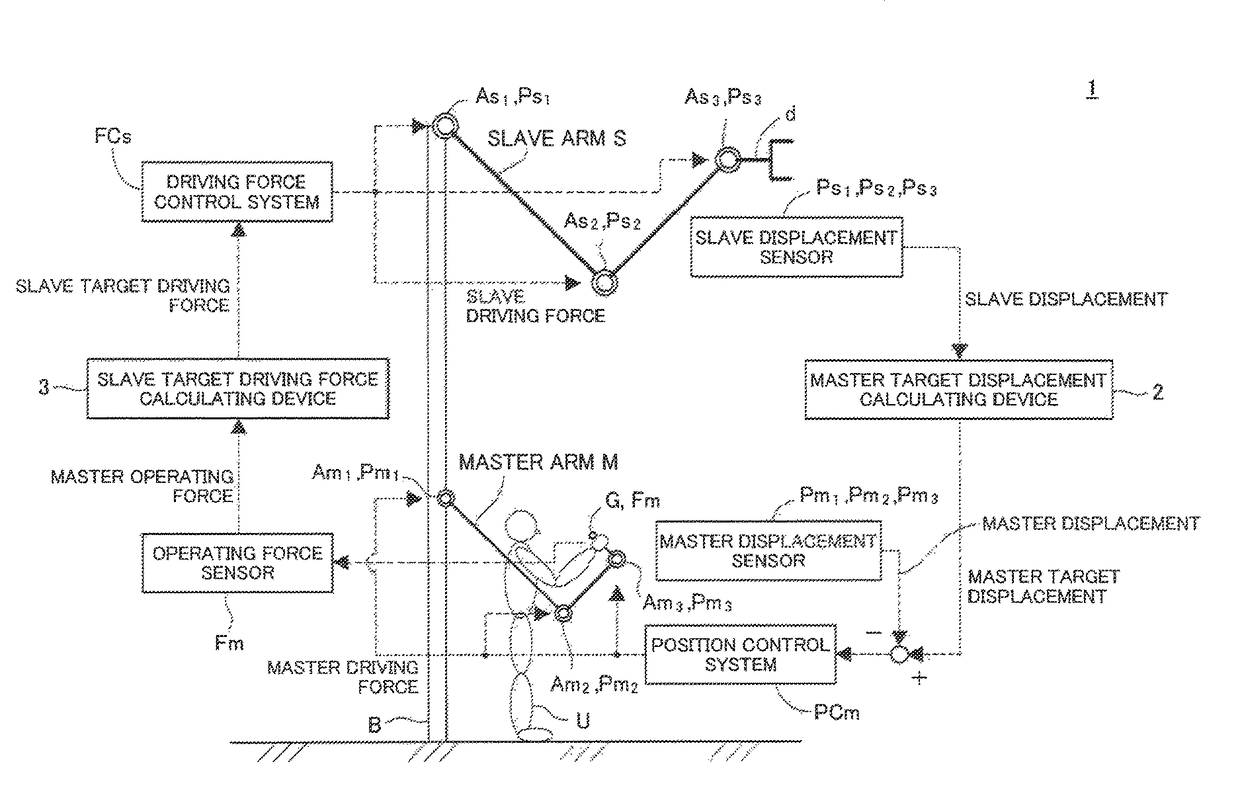
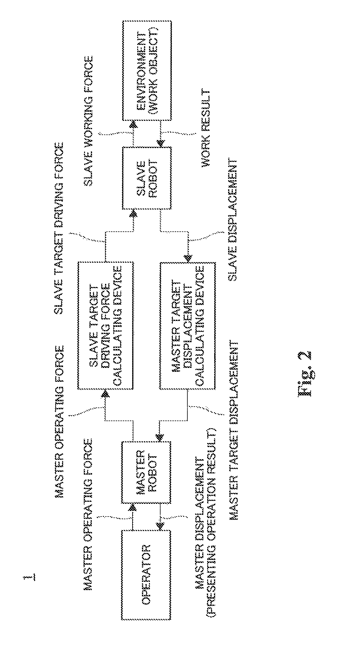
The mechanical master-slave system is advantageous in that the operator can have a direct feel of operation, but also disadvantageous in that: the degree of freedom in mechanism design is limited because of geometric restrictions between the operator and the master robot and also between the operator and the slave robot; the system naturally feels heavy to manipulate because the system is driven by
human power; and further, the system has trouble in ensuring safety when abnormalities arise.
However, for implementation reasons, the stability of bilateral control decreases as the force control
gain Kf increases, and therefore, it is difficult to eliminate the influence of the master dynamics on the master operating force fm, so that complete transparency cannot be achieved.
Such influences can be reduced to a negligible degree by increasing the force control
gain Kf, but for implementation reasons, even the increased stability of the bilateral control can be weakened as the force control
gain Kf increases, and therefore, even the parallel bilateral control cannot achieve complete transparency.
Information about the slave working force fs is required for control, and therefore, application to a system in which the working
force sensor cannot be mounted on the slave robot is not possible.
Control drives the system in accordance with
displacement error of the master robot, and therefore, it is necessary to set the
inertia and the friction of the master robot as little as possible, such that
displacement error of the master robot can be readily generated by
human power, i.e., high backdrivability is ensured, resulting in difficulty in achieving a highly accurate mechanism.
The slave robot is always connected to the master robot, and therefore, there is a risk that unstable behavior might be excited in the system solely by an external force applied to the slave robot, even without the operator manipulating the master robot.
A command value for the slave robot is position-related, and the slave dynamics need to be cancelled by positional control, which imposes a large burden on the
control system.
In addition, the control law based on the positional control does not necessarily allow another control law to be superimposed thereon.
When positional control in the work coordinate system is applied to the slave robot, a
singular configuration problem might arise, so that control failure might occur when the posture of the slave robot approaches a singular configuration.
However, some systems often involve difficulty in mounting the working
force sensor on the working end of the slave robot.
However, multi-axis force sensors, which are generally used as working force sensors, are delicate and expensive, and therefore, it is difficult to
mount such a sensor on the working end of the high-power slave robot.
Moreover, in the case of a master-slave system serving as a surgical robotic system, the slave robot is required to be invasive to the
human body, and the hardware thereof needs to be subjected to high-level cleaning, disinfection, and sterilization (
autoclave sterilization).
It is difficult to
mount a multi-axis
force sensor, which is a complex electronic device, on the working end of such a slave robot.
Under such circumstances, in the case of the conventional bilateral control, the master robot is naturally a powerless and delicate mechanism with a low
reduction ratio.
This means that the master robot tends to lack the rigidity and output power required to provide a reaction force to the operator with high accuracy.
However, to realize such ideal responses, all dynamics of the master-slave system, along with
inertia, need to be eliminated, which imposes a large burden on the
control system, resulting in a
high probability of unstable bilateral control (see Non-
Patent Document 3).
In the case of a system making “transparency”, rather than “projectivity”, as a norm, the operator is not presented with the
scale effect of the slave dynamics, and therefore, it is not expected that the operator performs such efficient and optimal manipulation.
Moreover, depending on the situation, there is a risk of unstable behavior being excited in the master-slave system solely by the external force −fs applied to the slave robot.
24 that in the case of both the force-reflecting type and the force-reflecting
servo bilateral control, when the operator takes his / her
hand off the operating end of the master robot, the system tends to exhibit unstable behavior.
Accordingly, to accurately reflect the operator's will in the hydraulic or
pneumatic actuator using the conventional bilateral control, it is necessary to apply a high-level and complicated positional control law, and implementing such a control law is expected to be difficult.
In the case where the slave robot is position-controlled, it is not necessarily possible to simply superimpose such control laws on each other, as described earlier.
In the case of a single-structure master-slave system, there are limitations to enhancing both
operability and workability.
In general, when a robot is position-controlled in the work coordinate system, the singular configuration problem occurs.
At the singular configuration, the direction of the movement of the robot in the work coordinate system is limited.
In the case where the robot's target trajectory is determined in the work coordinate system, the joint velocity for realizing the target trajectory becomes excessively high in the vicinity of the singular configuration.
In addition, the actual robot can only have a limited joint velocity, so that there is a possibility where positional control in the work coordinate system might fail in the vicinity of the singular configuration.
This is physical failure accompanied by coordinate transformation.
Accordingly, such positional control failure cannot be prevented by computational contrivance.
In the conventional master-slave systems, the slave robot is position-controlled, but if the positional control is performed in the work coordinate system, the singular configuration problem occurs.
More specifically, positional control failure occurs in the vicinity of the singular configuration unless approach to the vicinity of the singular configuration is avoided.
On the other hand, if the slave robot is caused to move so as to avoid the vicinity of the singular configuration in order not to risk failure, additional disadvantages which are difficult to overcome arise as follows:
ii) the singular configuration for the slave robot cannot be positively utilized for task achievement.
That is, even by using the approaches of Non-Patent Documents 6 and 7, it is still not possible to overcome the aforementioned disadvantages i) and ii).
However, although no failure occurs, the joint velocity is still limited, and therefore, detriment to
operability in the vicinity of the singular configuration is unavoidable.
These descriptions suggest that the common technical knowledge in the art is that implementation of the “position-force loop” is extremely difficult or even impossible.


