
Solid battery

a battery and solid state technology, applied in the field of solid state batteries, to achieve the effect of inhibiting the short circuit, and preventing the occurrence of short circuits

Active Publication Date: 2017-12-26
TOYOTA JIDOSHA KK
View PDF7 Cites 3 Cited by
  • Summary
  • Abstract
  • Description
  • Claims
  • Application Information

AI Technical Summary

Benefits of technology

The present invention is about a solid battery that can prevent short circuits between electrodes. The battery has several layers, including a solid electrolyte layer, and insulating layers on the outer edges of each layer. Even if the outer edge of the electrodes chips off and falls, the short circuit can be prevented. The insulating layers are also thick enough to prevent broken parts of the solid electrolyte layer from causing short circuits. Additionally, the size of the electrodes can be made larger to further inhibit short circuits. This design ensures the battery's safety and reliability.

Problems solved by technology

However, since commonly used electrolytic solutions are flammable, it is necessary to mount a system to ensure safety.

Method used


Image

  • Solid battery
  • Solid battery
  • Solid battery

Examples


Embodiment Construction

[0028]Hereinafter, a case in which the battery of the present invention is a lithium-ion secondary battery will be described with reference to the drawings. Herein, it should be noted that the embodiments shown below are examples of the present invention and that the present invention is not limited to these embodiments.

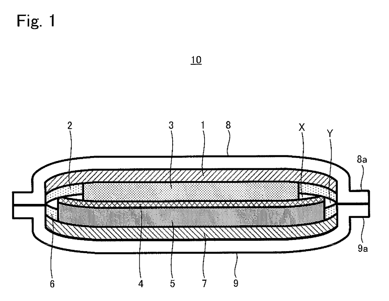
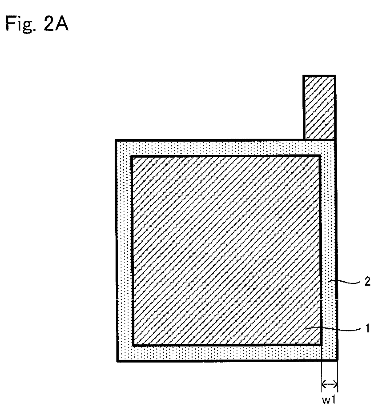
[0029]FIG. 1 is a cross-sectional view illustrating a solid battery 10 of the present invention. FIGS. 2A to 2D are views illustrating manufacturing steps of the solid battery 10. The top / bottom direction of the drawing sheet of FIG. 1 and the back / front direction of the drawing sheets of FIGS. 2A to 2D are the lamination direction.

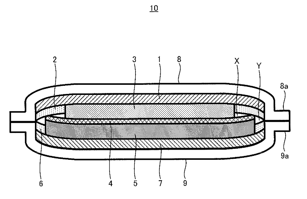
[0030]As shown in FIG. 1, the solid battery 10 has: a cathode current collector 1; a cathode layer 3 formed on a surface of the cathode current collector 1; a first insulating layer 2 disposed on an outer perimeter of the cathode layer 3; a solid electrolyte layer 4; an anode layer 5 disposed on an opposite side of the cathode layer 3 with...


PUM

PropertyMeasurementUnit
thicknessaaaaaaaaaa
perimeteraaaaaaaaaa
outer perimeteraaaaaaaaaa

Abstract

A solid battery has a first electrode layer, second electrode layer, and solid electrolyte layer disposed therebetween. A first insulating layer is disposed on an outer perimeter of the first electrode layer; a lamination face of the first electrode layer taking a lamination direction of the first electrode layer, the solid electrolyte layer, and the second electrode layer as a normal direction is smaller than that of the solid electrolyte layer; from the lamination direction, an outer edge of the solid electrolyte layer is positioned on the first electrode layer outer perimeter and an outer edge of the first insulating layer is positioned on an outer perimeter of the solid electrolyte layer; and the first electrode layer, the first insulating layer, and the solid electrolyte layer are disposed such that the outer edge of the first insulating layer and an end of the solid electrolyte layer contact each other.

Description

TECHNICAL FIELD[0001]The present invention relates to a solid battery having a pair of electrode layers and a solid electrolyte layer disposed between the pair of electrode layers.BACKGROUND ART[0002]A lithium-ion secondary battery (hereinafter sometimes simply referred to as a “battery”) has characteristics that it has a higher energy density than other secondary batteries and can be operated at a high voltage. Therefore, it is used for information devices such as cellular phones as it can be easily reduced in size and weight; and nowadays there is an increasing demand for the lithium-ion secondary battery to be used as a power source for large-scale apparatuses such as electric vehicles and hybrid vehicles.[0003]The lithium-ion secondary battery has a cathode layer and an anode layer (a pair of electrode layers), and an electrolyte layer disposed therebetween. For example, a non-aqueous liquid substance or a solid substance is known to be used as an electrolyte in the electrolyte ...

Claims


Application Information

Patent Timeline
Patent Type & Authority Patents(United States)
IPC IPC(8): H01M2/18H01M10/0565H01M10/0585H01M2/08H01M10/0525H01M50/463
CPCH01M2/18H01M2/08H01M10/0565H01M10/0585H01M10/0525Y02T10/7011H01M50/463Y02E60/10Y02P70/50Y02T10/70
Inventor TANAKA, KATSUHISA
Owner TOYOTA JIDOSHA KK
Learn More