Excitation light source device and optical transmission system
a light source device and light source technology, applied in the direction of optical elements, transmission monitoring, instruments, etc., can solve the problems of increasing the size and cost of the optical amplification device, the inability to measure the abnormal state the damage of the transmission line, so as to reduce the intensity of the raman excitation light
- Summary
- Abstract
- Description
- Claims
- Application Information
AI Technical Summary
Benefits of technology
Problems solved by technology
Method used
Image
Examples
embodiment 1
[0030]In an Embodiment 1, is explained that a system for detecting abnormality in a transmission line based on the state of supply of Raman excitation light (hereinafter, simply referred to as “excitation light”) and the intensity of amplified spontaneous emission noise caused by the excitation light.
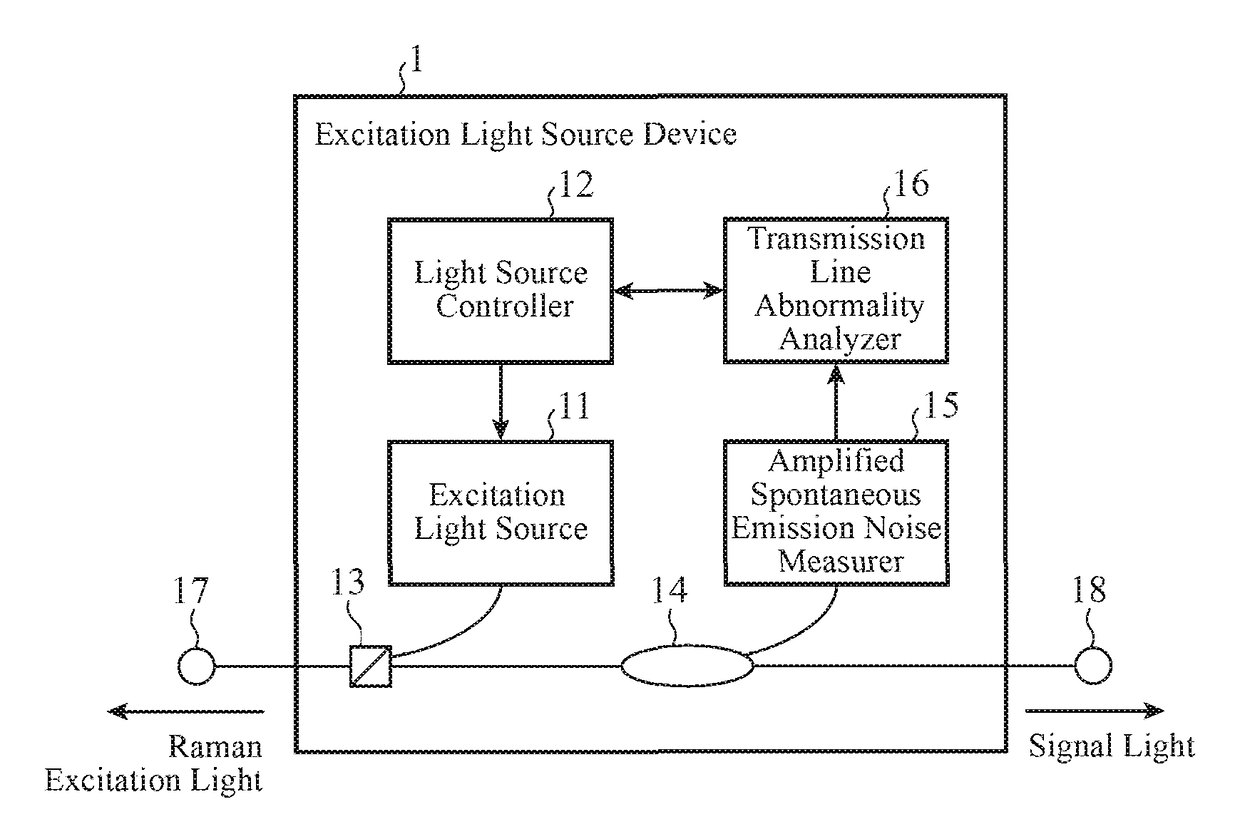
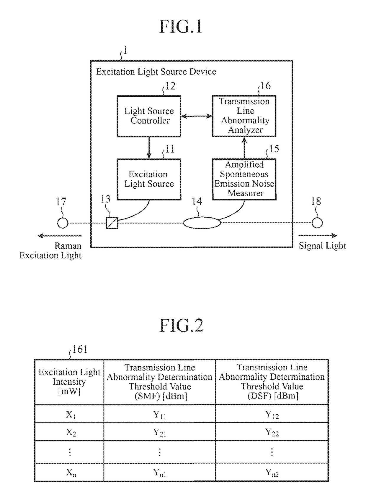
[0031]FIG. 1 is a diagram representing a configuration of an excitation light source device 1 according to the Embodiment 1 of the invention.
[0032]The excitation light source device 1 is to output excitation light that amplifies signal light to a transmission line on which the signal light is transmitted. As shown in FIG. 1, the excitation light source device 1 includes an excitation light source 11, a light source controller 12, a multiplexer 13, a branching device 14, an amplified spontaneous emission noise measurer 15, and a transmission line abnormality analyzer 16.
[0033]Note that the transmission line is implemented by an optical fiber. Signal light (main signal light) flowing thro...
embodiment 2
[0060]In an Embodiment 2, it is explained that a system for detecting abnormality in a transmission line on a bases of the state of supply of excitation light, and Raman gain which is given to signal light and is caused by the excitation light.
[0061]FIG. 6 is a diagram representing a configuration of an excitation light source device 1b according to the Embodiment 2 of the invention. The excitation light source device 1b according to the Embodiment 2 shown in FIG. 6 is configured such that, an amplified spontaneous emission noise measurer 15 of an excitation light source device 1 according to the Embodiment 1 shown in FIG. 1 is removed, and a Raman gain measurer 19 is introduced. Furthermore, a light source controller 12 and a transmission line abnormality analyzer 16 are changed to a light source controller 12b and a transmission line abnormality analyzer 16b. Other configurations are the same and thus are denoted by the same reference signs, and description thereof is omitted.
[006...
embodiment 3
[0081]In an Embodiment 3, it is explained that a system for controlling the intensity of excitation light to obtain Raman gain following a target value, and detecting abnormality in a transmission line based on the intensity of excitation light controlled at that time.
[0082]FIG. 11 is a configuration diagram representing an excitation light source device 1c according to the Embodiment 3 of the invention. The excitation light source device 1c according to the Embodiment 3 shown in FIG. 11 is such that a light source controller 12b and a transmission line abnormality analyzer 16b of an excitation light source device 1b according to the Embodiment 2 shown in FIG. 6 are changed to a light source controller 12c and a transmission line abnormality analyzer 16c. Other configurations are the same and thus are denoted by the same reference signs and description thereof is omitted.
[0083]The light source controller 12c is to control the intensity of excitation light generated by an excitation ...
PUM
 Abstract
Description
Claims
Application Information
 - R&D
- Intellectual Property
- Life Sciences
- Materials
- Tech Scout
- Unparalleled Data Quality
- Higher Quality Content
- 60% Fewer Hallucinations
Browse by: Latest US Patents, China's latest patents, Technical Efficacy Thesaurus, Application Domain, Technology Topic, Popular Technical Reports.
© 2025 PatSnap. All rights reserved.Legal|Privacy policy|Modern Slavery Act Transparency Statement|Sitemap|About US| Contact US: help@patsnap.com


