
Apparatus and a system for automatic tool change by threading engagement for a CNC milling machine

a technology of automatic tool change and cnc milling machine, which is applied in the direction of electric programme control, program control, instruments, etc., can solve the problems of not perfecting traditional techniques

Active Publication Date: 2017-11-28
URIARTE JORGE
View PDF10 Cites 0 Cited by
  • Summary
  • Abstract
  • Description
  • Claims
  • Application Information

AI Technical Summary

Benefits of technology

The patent text describes an invention related to automatic tool changing in a CNC milling machine. The invention is about improving the process of changing tooling on a machine by using a threaded engagement system. The technical effects of the invention include reducing the time it takes to change tools, making the process more efficient, and making it easier to use for operators. The invention also includes various methods for securely holding tools in place during machining operations. The prior art includes various examples of collet arbors and spindle and tool holder systems, but the invention offers more optimal approaches for these tasks.

Problems solved by technology

In view of the foregoing, it is clear that these traditional techniques are not perfect and leave room for more optimal approaches.

Method used


Image

  • Apparatus and a system for automatic tool change by threading engagement for a CNC milling machine
  • Apparatus and a system for automatic tool change by threading engagement for a CNC milling machine
  • Apparatus and a system for automatic tool change by threading engagement for a CNC milling machine

Examples


Embodiment Construction

[0021]The present invention is best understood by reference to the detailed figures and description set forth herein.

[0022]Embodiments of the invention are discussed below with reference to the Figures. However, those skilled in the art will readily appreciate that the detailed description given herein with respect to these figures is for explanatory purposes as the invention extends beyond these limited embodiments. For example, it should be appreciated that those skilled in the art will, in light of the teachings of the present invention, recognize a multiplicity of alternate and suitable approaches, depending upon the needs of the particular application, to implement the functionality of any given detail described herein, beyond the particular implementation choices in the following embodiments described and shown. That is, there are modifications and variations of the invention that are too numerous to be listed but that all fit within the scope of the invention. Also, singular ...


PUM

PropertyMeasurementUnit
angleaaaaaaaaaa
rotationaaaaaaaaaa
rotation rateaaaaaaaaaa

Abstract

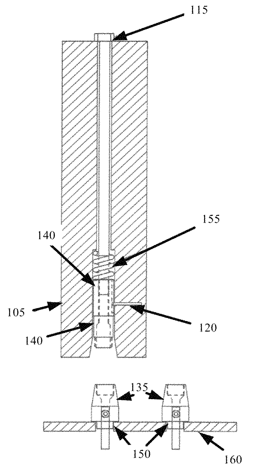
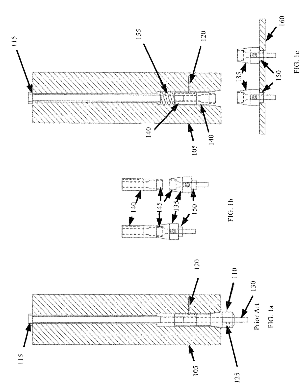
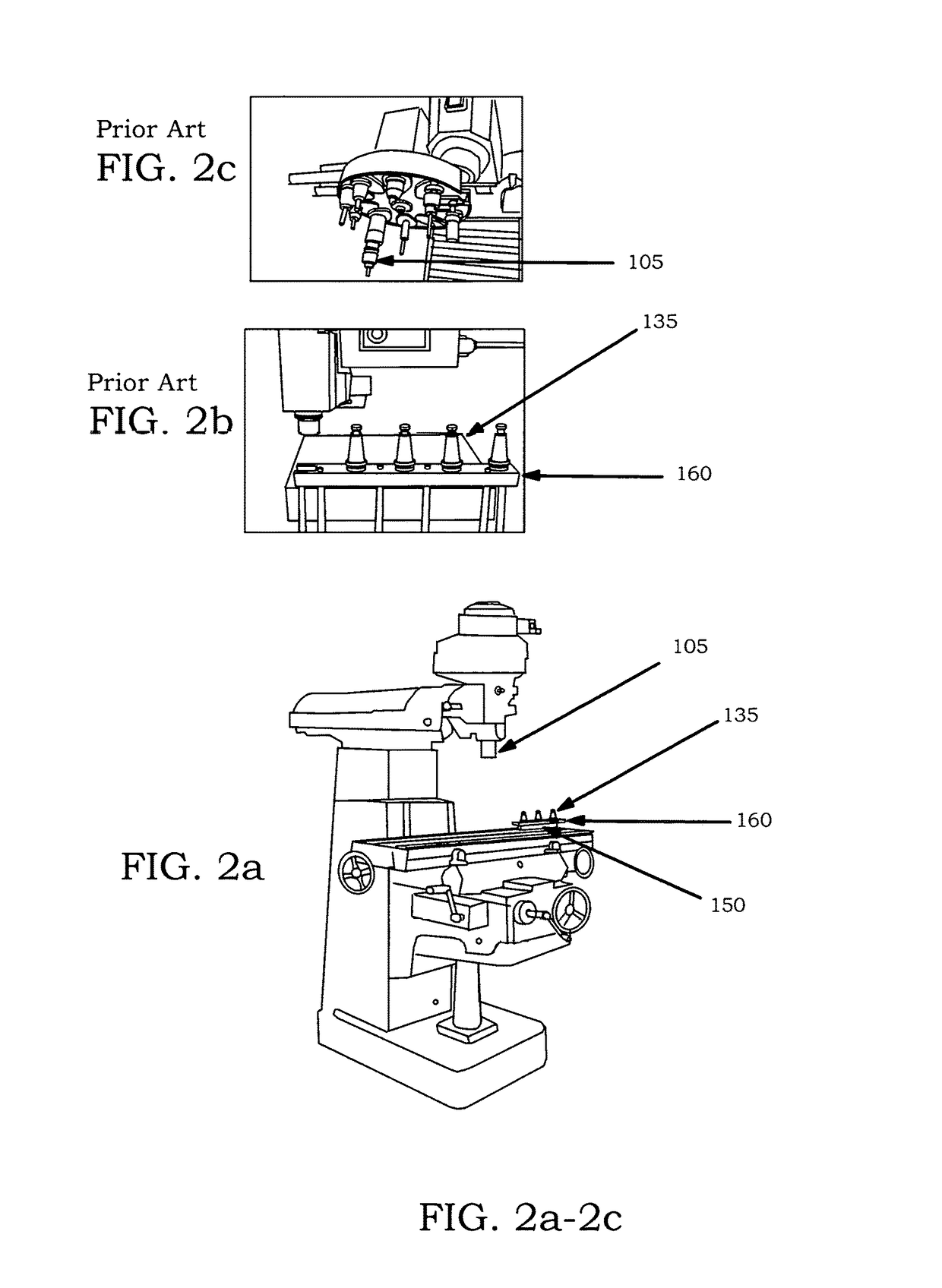
An apparatus and a system comprise a collet comprising a top portion and a bottom portion. The top portion comprises a threading means. The bottom portion at least comprises means for holding the collet from rotating and means for retaining an end mill. A master comprises a top portion and a bottom portion. The top portion is configured for engagement with a spindle of a milling machine. The bottom portion comprises a threading means for engagement with the threading means of the collet, wherein the master is retained by the spindle and the collet engages and disengages the master by rotation of the spindle. The milling machine operates under computer control during engagement and disengagement of the collet from the master.

Description

CROSS-REFERENCE TO RELATED APPLICATIONS[0001]Not applicable.RELATED CO-PENDING U.S. PATENT APPLICATIONS[0002]Not applicable.FEDERALLY SPONSORED RESEARCH OR DEVELOPMENT[0003]Not applicable.REFERENCE TO SEQUENCE LISTING, A TABLE, OR A COMPUTER LISTING APPENDIX[0004]Not applicable.COPYRIGHT NOTICE[0005]A portion of the disclosure of this patent document contains material that is subject to copyright protection by the author thereof. The copyright owner has no objection to the facsimile reproduction by anyone of the patent document or patent disclosure for the purposes of referencing as patent prior art, as it appears in the Patent and Trademark Office, patent file or records, but otherwise reserves all copyright rights whatsoever.FIELD OF THE INVENTION[0006]One or more embodiments of the invention generally relate to automatic tool changing by threading engagement for a CNC Milling machine. More particularly, the invention relates to machine tooling functions for hole threading, or rig...

Claims


Application Information

Patent Timeline
Patent Type & Authority Patents(United States)
IPC IPC(8): B23Q3/157B23Q3/155G05B19/18B23Q5/10B23B31/26B23Q5/00
CPCB23Q3/15706B23Q3/15503B23Q3/15553B23Q5/10G05B19/182B23Q3/1552Y10T483/1798B23B31/266B23Q3/15536B23Q2005/005G05B2219/45145G05B2219/50245Y10T409/309464Y10T483/10Y10T483/12Y10T483/132Y10T483/179Y10T483/1793Y10T483/1795B23Q3/12
Inventor URIARTE, JORGE
Owner URIARTE JORGE
Learn More