
Toner

a technology of toner and core resin, applied in the field of toner, can solve the problems of low-temperature fixability, prone to cold offset, and difficult to ensure the heat exchange of the core resin, and achieve excellent low-temperature fixability and storage stability, environmental stability, and durability

Active Publication Date: 2017-11-21
CANON KK
View PDF83 Cites 33 Cited by
  • Summary
  • Abstract
  • Description
  • Claims
  • Application Information

AI Technical Summary

Benefits of technology

[0018]The present invention has been made in view of such problems as described above, and an object of the present invention is to provide a toner that is excellent in charging stability, environmental stability, and durability, and is excellent in low-temperature fixability and storage stability.

Problems solved by technology

However, the inventors of the present invention have investigated the toner of Japanese Patent Application Laid-Open No. 2006-91283, and as a result, have found that the toner involves a problem in terms of low-temperature fixability.
Accordingly, the exudation of a wax at the time of fixation is inhibited and hence a cold offset is liable to occur.
Accordingly, it is not easy for the core resin to receive sufficient heat from a heat roller at the time of the fixation.
In addition, when the toner of Japanese Patent Application Laid-Open No. 2010-132851 was evaluated for its chargeability, the chargeability was susceptible to a humidity and hence expected environmental stability could not be obtained.
In addition, it has been found that when the toner of Japanese Patent Application Laid-Open No. 2010-168522 was evaluated, satisfactory environmental stability was obtained in its charging performance but expected durability was not obtained.
Accordingly, the surface of the toner particle is liable to soften and hence the durability is not obtained.
Further, it has been found that when the toner of Japanese Patent Application Laid-Open No. 2013-137495 was subjected to a durability test after the toner had been left to stand under a severe environment for a long time period, an image failure occurred in some cases and hence the effect of environmental stability was not necessarily sufficient.

Method used


Image

  • Toner
  • Toner
  • Toner

Examples


example 1

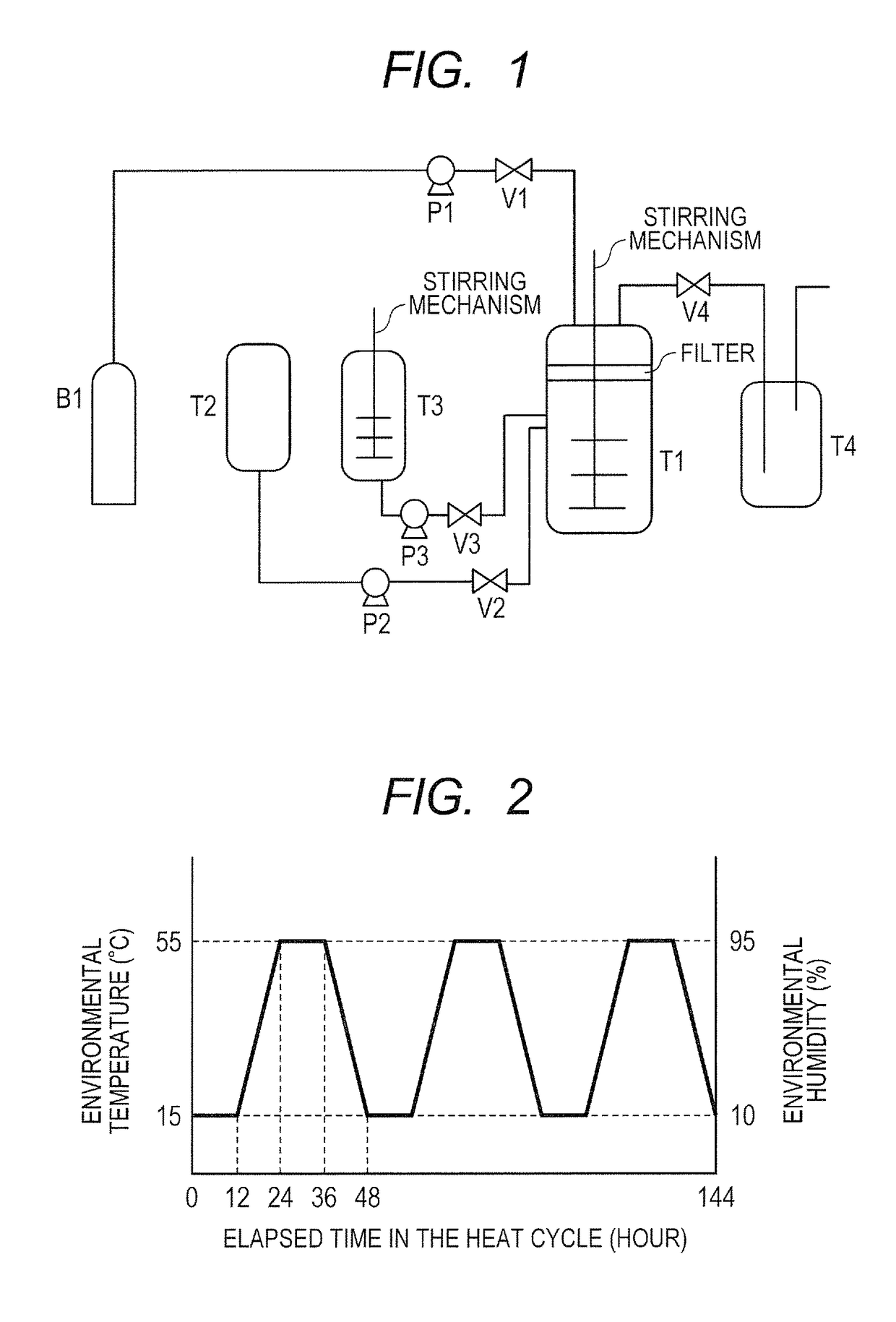
[0319]In an apparatus illustrated in FIG. 1, first, valves V1, V2, and V3 and a pressure-adjusting valve V4 were closed. 18.0 Parts by mass of the resin fine particle dispersion liquid 16 for forming an intermediate layer containing the resin “B” was loaded into a pressure-resistant granulation tank T1 including a filter for capturing toner particle and a stirring mechanism, and the internal temperature of the tank was adjusted to 40° C. Next, the valve V1 was opened, carbon dioxide (purity: 99.99%) was introduced from a carbon dioxide bomb B1 into the granulation tank T1 with a pump P1, and the valve V1 was closed when the internal pressure of the tank reached 2.0 MPa.

[0320]Meanwhile, the block polymer solution 1, the colorant dispersion liquid 1, and the wax dispersion liquid 1 were loaded into a resin solution tank T3 to prepare a resin solution, and then the internal temperature of the tank was adjusted to 40° C. Next, the valve V3 was opened, and the resin solution of the resin...

example 28

[0330]In an apparatus illustrated in FIG. 1, first, valves V1, V2, and V3 and a pressure-adjusting valve V4 were closed. Then, 18.0 parts by mass of the resin fine particle dispersion liquid 16 for forming a first intermediate layer containing the resin “B” was loaded into a pressure-resistant granulation tank T1 including a filter for capturing toner particle and a stirring mechanism, and the internal temperature of the tank was adjusted to 40° C. Next, the valve V1 was opened, carbon dioxide (purity: 99.99%) was introduced from a carbon dioxide bomb B1 into the granulation tank T1 with a pump P1, and the valve V1 was closed when the internal pressure of the tank reached 2.0 MPa.

[0331]Meanwhile, the block polymer solution 1, the colorant dispersion liquid 1, and the wax dispersion liquid 1 were loaded into a resin solution tank T3 to prepare a resin solution, and then the internal temperature of the tank was adjusted to 40° C. Next, the valve V3 was opened, and the resin solution o...

example 29

[0337]In an apparatus illustrated in FIG. 1, first, valves V1, V2, and V3 and a pressure-adjusting valve V4 were closed. Then, 18.0 parts by mass of the resin fine particle dispersion liquid 12 for forming a shell layer containing the resin “A” was loaded into a pressure-resistant granulation tank T1 including a filter for capturing toner particle and a stirring mechanism, and the internal temperature of the tank was adjusted to 40° C. Next, the valve V1 was opened, carbon dioxide (purity: 99.99%) was introduced from a carbon dioxide bomb B1 into the granulation tank T1 with a pump P1, and the valve V1 was closed when the internal pressure of the tank reached 2.0 MPa.

[0338]Meanwhile, the block polymer solution 1, the colorant dispersion liquid 1, and the wax dispersion liquid 1 were loaded into a resin solution tank T3 to prepare a resin solution, and then the internal temperature of the tank was adjusted to 40° C. Next, the valve V3 was opened, and the resin solution of the resin s...


PUM


Abstract

Provided is a toner including toner particle, the toner particle having a core-shell structure having: a core containing a core resin, a colorant, and a wax; and a shell layer containing a resin “A” on a surface of the core, in which: the resin “A” contains a segment having an organopolysiloxane structure; the toner particle has an amount of Si derived from the organopolysiloxane structure of 6.0 or more and 10.0 or less, the amount of Si being measured by X-ray photoelectron spectroscopy; the resin “A” is a polymer of a monomer composition containing a monomer “a” having two or more polymerizable unsaturated groups in one molecule thereof; and the monomer “a” satisfies the following formula (1).(Xa−1.0)×Ya≧3.0×10⁻⁵  (1)

Description

BACKGROUND OF THE INVENTION[0001]Field of the Invention[0002]The present invention relates to a toner to be used in an electrophotographic method, an electrostatic recording method, and a toner jet type recording method.[0003]Description of the Related Art[0004]As a toner for an improvement in low-temperature fixability and storage stability of the toner, there is a toner particle having a core-shell structure in which the surface of a resin serving as a core is covered with a shell resin.[0005]Furthermore, a method involving using a hydrophobic material that is hardly affected by a temperature and a humidity as the shell resin covering the surface of the toner particle is conceivable as a method of improving the environmental stability of the toner. An organopolysiloxane has been known as a material having low interfacial tension.[0006]Therefore, the introduction of an organopolysiloxane structure into the shell resin of the toner particle is expected to be capable of imparting cha...

Claims


Application Information

Patent Timeline
Patent Type & Authority Patents(United States)
IPC IPC(8): G03G9/093
CPCG03G9/09321G03G9/09378G03G9/09342G03G9/09328
Inventor TOYOIZUMI, NORITAKAKOSAKI, YUSUKEKINUMATSU, TETSUYAAOKI, KENJIWATANABE, SHUNTAROKAYA, TAKAAKITANI, ATSUSHIKASUYA, TAKASHIGE
Owner CANON KK
Learn More