
Combinatorial light string plug and receptacle

a light string and plug-in technology, applied in the field of light strings, can solve the problems of not being able to efficiently transmit data and power, not being able to meet the requirements of plug-in receptacles, etc., and achieves the effects of enhancing protection against arcing, reducing the number of components, and increasing reliability

Inactive Publication Date: 2017-11-07
WILLIS ELECTRIC
View PDF15 Cites 0 Cited by
  • Summary
  • Abstract
  • Description
  • Claims
  • Application Information

AI Technical Summary

Benefits of technology

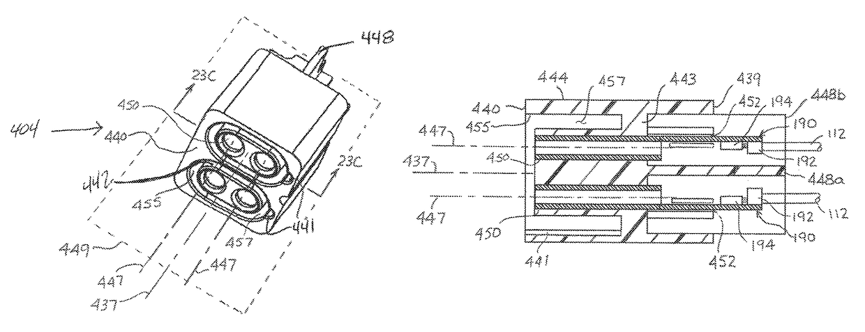
This patent describes a new connector that helps protect against arcing when connecting light strings. The connector uses dielectric barriers to isolate the terminals, which makes it fast and easy to assemble. The connector also has a modular system that allows for easy replacement of malfunctioning light strings without having to replace the entire string. The modularity also allows for a coordinated lighting effect between the string of lights. Additionally, this patent describes the use of a chain of light strings with local controllers that communicate with each other to create a coordinated effect. This chain of lights provides full power to each string and eliminates line losses associated with long runs of multiple lights.

Problems solved by technology

Decorative light strings having controllers often do not include plug receptacles at the one end, and cannot be connected end-to-end with other light strings thus requiring numerous controllers and light string sets that are each individually programmed or set.
Furthermore, of the few known decorative light strings with controllers that are configured to connect to other light strings, the connectors are not standard, and the plugs and receptacles are not typically configured to efficiently transmit data and power.

Method used


Image

  • Combinatorial light string plug and receptacle
  • Combinatorial light string plug and receptacle
  • Combinatorial light string plug and receptacle

Examples


Embodiment Construction

[0127]Described herein are decorative light strings with controllers, the light strings having plug assemblies and receptacle assemblies where the plugs and receptacles are provided with combinatorial power and data terminals.

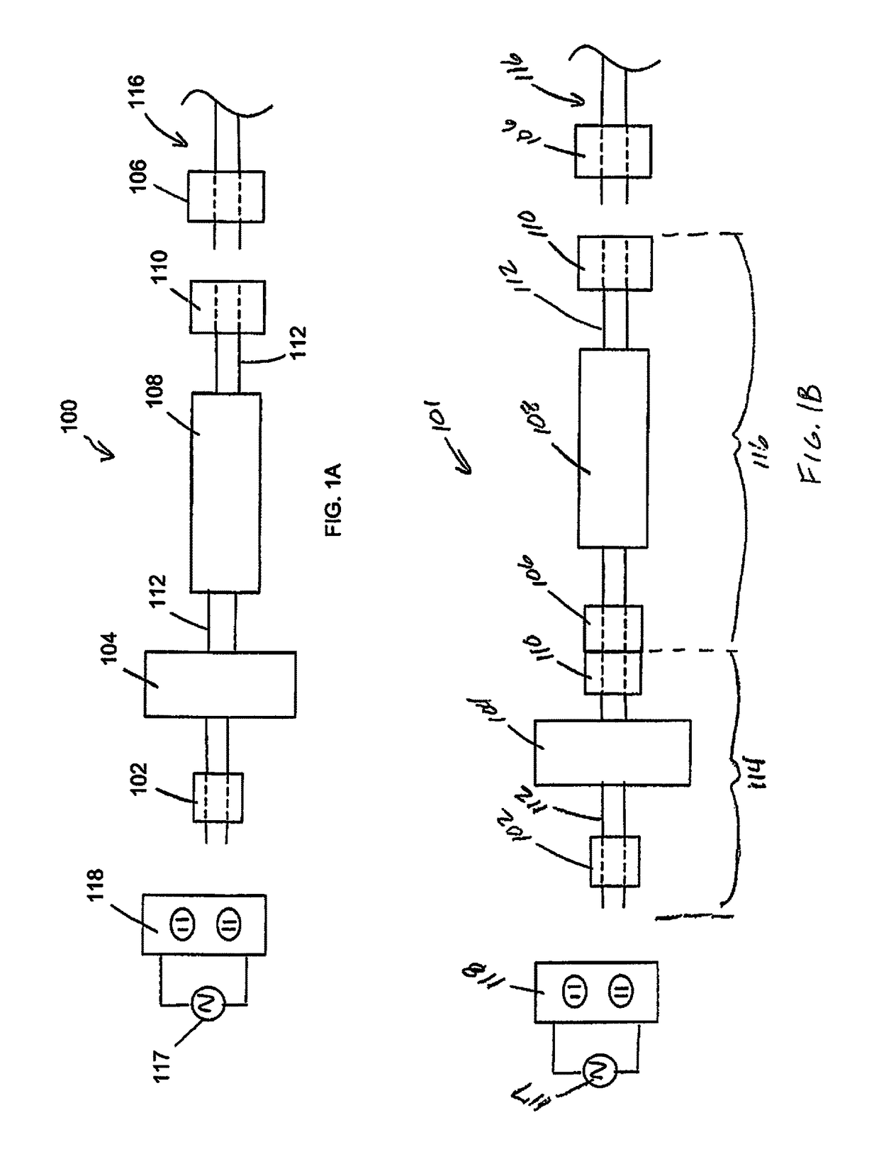
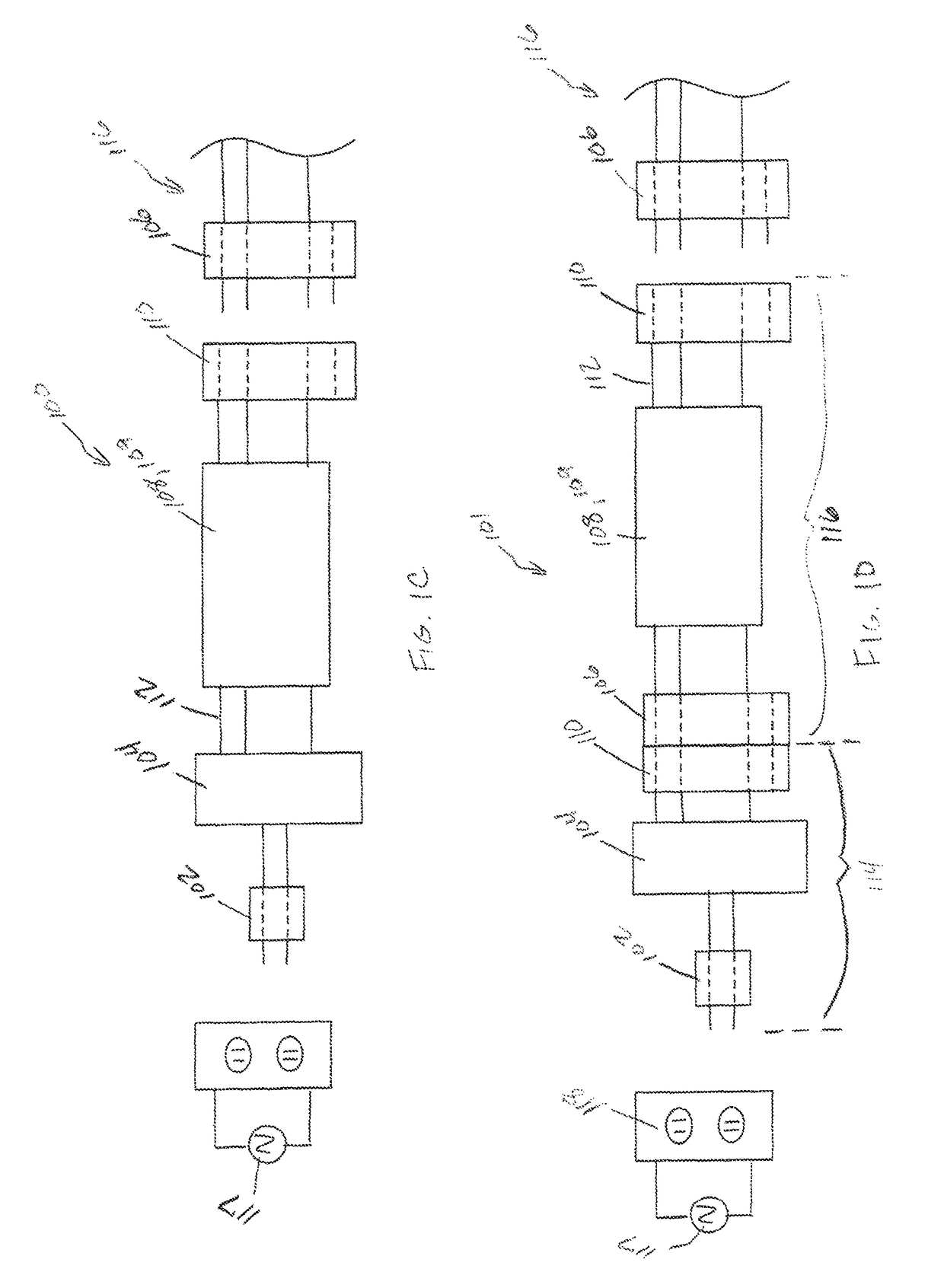
[0128]Referring to FIGS. 1A, 1C, and 1E, light strings 100 are depicted according to embodiments of the disclosure. The light strings 100 may include a standard two blade plug 102, a controller 104, a light array 108, 109, a receptacle assembly 110 where the receptacle can further comprise two- to four-female electrical conductors, and wiring 112. Standard plug 102 can be a two blade plug 102 where the two blades are primary power terminals and connect to an AC power source 117 through a standard wall outlet 118.

[0129]Referring to FIGS. 1B, 1D, and 1F, light strings 101 are depicted according to embodiments of the disclosure. The light strings 101 may include two subassemblies, a controller subassembly 114 and a light string subassembly 116. In an embodiment, t...


PUM


Abstract

A connector having enhanced protection against arcing during live or “hot” connection of a plug assembly to a receptacle assembly. The terminals of the connector, including the connection point of exposed wiring, are electrically isolated from each other with dielectric barriers built in to the connector, such as polymer partitions. Accordingly, protection against arcing is provided in a connector that is assembled fast and inexpensively, without need for a time consuming installation of wire and terminal coatings or sleeves (e.g., “shrink tube”), and with greater reliability. The connector can be used in a modular system for decorative lighting and having a controller module that is not hard wired to a light string. Use of the controller module independent of any of the light strings enables the controller to be used with any light string or with a replacement light string, in the event that the immediately connected light string fails.

Description

RELATED APPLICATIONS[0001]This application claims the benefit of U.S. Provisional Patent Application No. 62 / 257,098 entitled “Combinatorial Light String Plug and Receptacle”, filed Nov. 18, 2015, the disclosure of which is incorporated by reference herein in its entirety.FIELD OF THE DISCLOSURE[0002]The disclosure relates to light strings, and in particular, to light strings comprised of LED lights wired in parallel. Specifically, the disclosure relates to light strings that can have a plurality of light arrays or a subsequent light string having arrays where each light array can operate independently of any other light array. More specifically, the disclosure relates to light strings having multi-function controllers allowing programming of color and motion, where the light strings can have plugs and receptacles whose terminals carry both power and data. Even more specifically, the disclosure relates to light string plugs having pin type terminals and light string socket receptacle...

Claims


Application Information

Patent Timeline
Patent Type & Authority Patents(United States)
IPC IPC(8): H01R13/506H01R13/432H01R13/46H01R24/20H01R13/717H01R24/28H01R13/11H01R13/516H01R13/64H01R4/18H01R13/05H01R107/00
CPCH01R13/64H01R4/185H01R13/052H01R13/111H01R13/46H01R13/7175H01R24/20H01R24/28H01R13/432H01R2107/00H01R13/6453H01R13/6456H01R24/22H01R24/30
Inventor CHEN, JOHNNY
Owner WILLIS ELECTRIC
Learn More