
Positive electrode for nonaqueous electrolyte secondary batteries, and nonaqueous electrolyte secondary battery

a technology of electrolyte secondary batteries and positive electrodes, which is applied in the direction of electrochemical generators, cell components, cell component details, etc., can solve the problems of deterioration of high-rate characteristics, many voids not only on the surface, and insufficient electric conductivity between particles, etc., to achieve efficient gas generation and efficient gas release

Active Publication Date: 2017-10-31
TOYOTA JIDOSHA KK
View PDF14 Cites 0 Cited by
  • Summary
  • Abstract
  • Description
  • Claims
  • Application Information

AI Technical Summary

Benefits of technology

The present invention helps generate gas efficiently and release it from the positive electrode layer of a nonaqueous electrolyte battery, while maintaining high-rate performance.

Problems solved by technology

However, when the particle diameter of positive electrode active material particles is increased as described above, electric conductivity in particles and between particles becomes insufficient.
As a result, the internal resistance of the nonaqueous electrolyte secondary battery increases, leading to deterioration of the high-rate characteristics, for example, at the time of discharging the battery at a large current.
However, the technique described in Patent Literature 1 has the following problem: microbubbles are added throughout the positive electrode mixture paste, and many voids exist not only on a surface of the positive electrode mixture layer but also in the vicinity of the current collector.
Therefore, electric conductivity in particles and between particles of the positive electrode active material becomes insufficient, and the internal resistance of the positive electrode increases, leading to deterioration of the high-rate characteristics of the nonaqueous electrolyte secondary battery.
As a result, generation of gas in the positive electrode mixture layer is suppressed at the time of overcharge, and the generated gas is hard to be released from the inside of the positive electrode mixture layer, which makes it difficult to reliably operate the current interrupt device.

Method used


Image

  • Positive electrode for nonaqueous electrolyte secondary batteries, and nonaqueous electrolyte secondary battery
  • Positive electrode for nonaqueous electrolyte secondary batteries, and nonaqueous electrolyte secondary battery
  • Positive electrode for nonaqueous electrolyte secondary batteries, and nonaqueous electrolyte secondary battery

Examples


example 1

[0051]A second positive electrode mixture paste for forming the second mixture layer 22B was prepared by using a positive electrode active material having an average particle diameter d50 of 5.7 μm and comprising a “lithium composite oxide (Li(Ni, Mn, Co)O2)” as a positive electrode active material, “acetylene black (AB)” as a conductive material, and “polyvinylidene fluoride (PVdF)” as a binding material; mixing the positive electrode active material, the conductive material and the binding material in a ratio (weight ratio) of 100:5:2; and kneading the mixture using “N-methyl-2-pyrrolidone (NMP)” as a solvent.

[0052]A first positive electrode mixture paste for forming the first mixture layer 22A was prepared by preparing a positive electrode mixture paste similar to the second positive electrode mixture paste except that a positive electrode active material having an average particle diameter d50 of 3.0 μm and comprising a “lithium composite oxide (Li(Ni, Mn, Co)O2)” was used as a ...

example 2

[0063]The positive electrode 13a of Example 2 was prepared in the same manner as in Example 1 except that the second positive electrode mixture paste of Example 1 was applied onto each of both surfaces of a 15 μm-thick aluminum foil as the current collector 21 in an amount of 13 mg / cm2, and the first positive electrode mixture paste of Example 1 was then applied in an amount of 2 mg / cm2 onto the second positive electrode mixture paste applied onto each of both surfaces of the aluminum foil. The nonaqueous electrolyte secondary battery 1 of Example 2 was formed in the same manner as in Example 1 except that the positive electrode 13a of Example 2 was used.

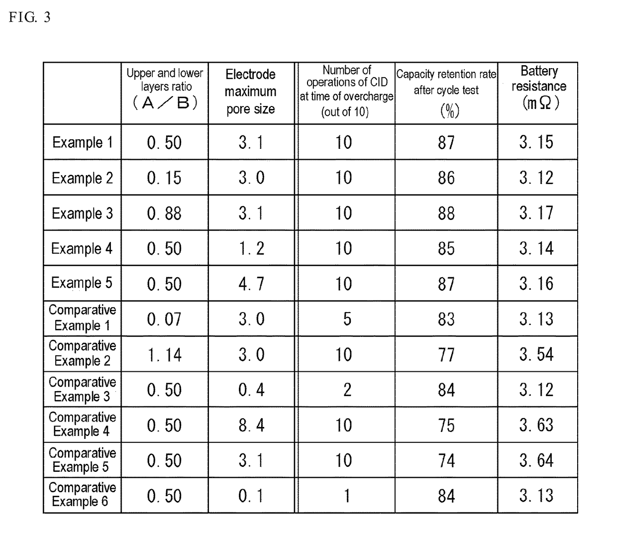
[0064]The ratio (A / B) of the thickness A of the first mixture layer 22A to the thickness B of the second mixture layer 22B in the positive electrode mixture layer 22 of the positive electrode 13a of Example 2 is 0.15.

[0065]When a pore size distribution in the positive electrode mixture layer 22 of the positive electrode 13a of Examp...

example 3

[0066]The positive electrode 13a of Example 3 was prepared in the same manner as in Example 1 except that the second positive electrode mixture paste of Example 1 was applied onto each of both surfaces of a 15 μm-thick aluminum foil as the current collector 21 in an amount of 8 mg / cm2, and the first positive electrode mixture paste of Example 1 was then applied in an amount of 7 mg / cm2 onto the second positive electrode mixture paste applied onto each of both surfaces of the aluminum foil. The nonaqueous electrolyte secondary battery 1 of Example 3 was formed in the same manner as in Example 1 except that the positive electrode 13a of Example 3 was used.

[0067]The ratio (A / B) of the thickness A of the first mixture layer 22A to the thickness B of the second mixture layer 22B in the positive electrode mixture layer 22 of the positive electrode 13a of Example 3 is 0.88.

[0068]When a pore size distribution in the positive electrode mixture layer 22 of the positive electrode 13a of Exampl...


PUM

PropertyMeasurementUnit
particle diameteraaaaaaaaaa
diameteraaaaaaaaaa

Abstract

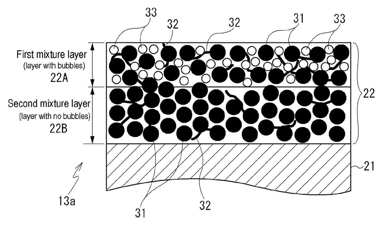
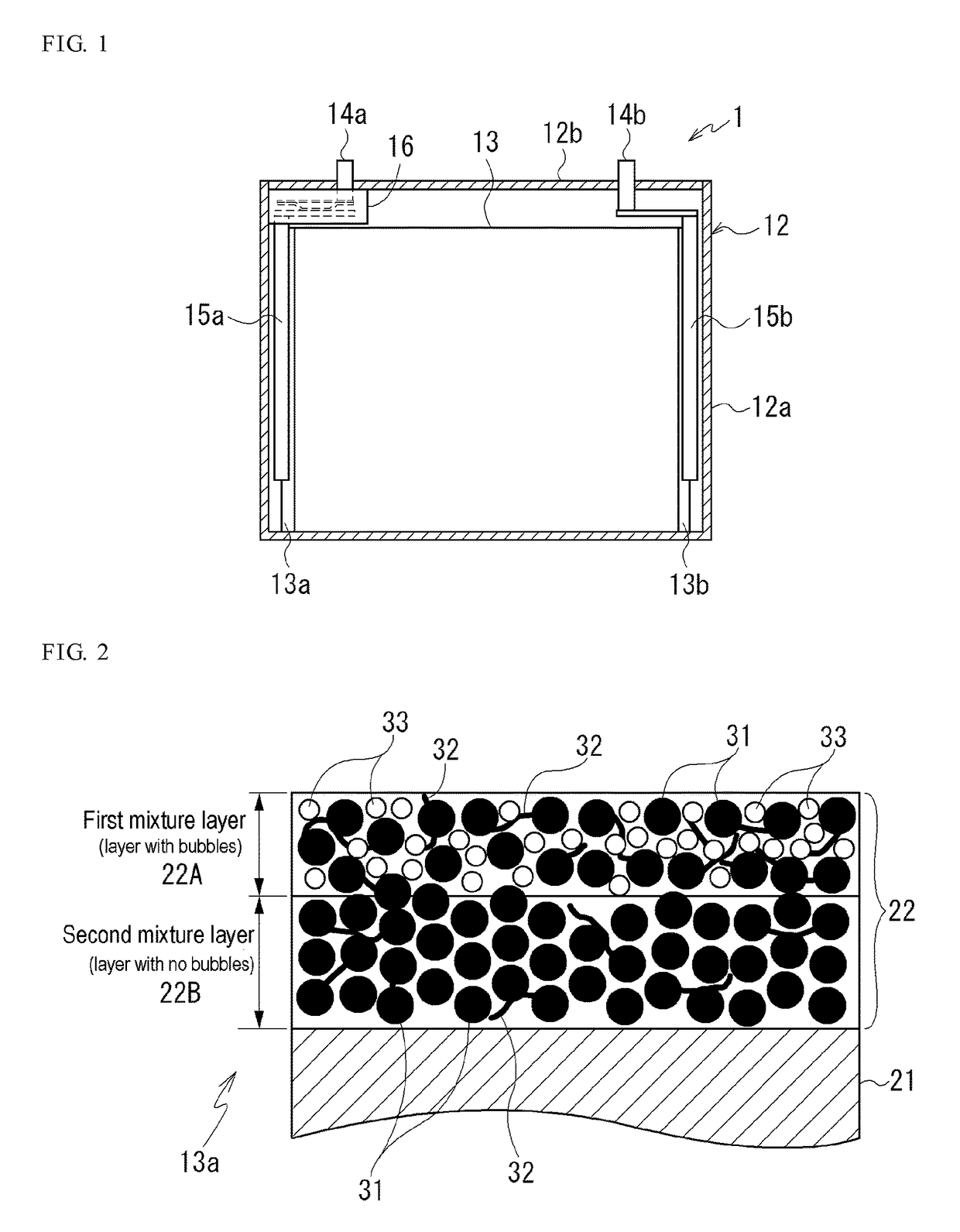
Provided is a positive electrode for nonaqueous electrolyte secondary batteries including a positive electrode mixture layer formed of a positive electrode mixture paste containing a positive electrode active material. The positive electrode active material has a particle diameter of 2 μm or more and less than 7 μm. The positive electrode mixture layer includes a first mixture layer in which a maximum diameter of pores formed between particles of the positive electrode active material is more than 1.0 μm and 5.0 μm or less, and a second mixture layer in which a maximum diameter of the pores is 1.0 μm or less. The second mixture layer is arranged closer to the current collector than the first mixture layer. A ratio of a thickness of the first mixture layer to a thickness of the second mixture layer is more than 0.1 and 1.0 or less.

Description

CROSS REFERENCE TO RELATED APPLICATIONS[0001]This is a National Stage of International Application No. PCT / JP2012 / 074300 filed Sep. 21, 2012, the contents of which are incorporated herein by reference in its entirety.TECHNICAL FIELD[0002]The present invention relates to a positive electrode for nonaqueous electrolyte secondary batteries, which is capable of efficiently generating gas in a positive electrode mixture layer at the time of overcharge while maintaining high-rate characteristics, and a nonaqueous electrolyte secondary battery.BACKGROUND ART[0003]Conventionally, in a nonaqueous electrolyte secondary battery such as a lithium ion secondary battery, for example, a positive electrode mixture paste obtained by kneading electrode materials such as a positive electrode active material, a conductive material and a binding material (binder) together with a solvent is applied to a current collector and dried to form a positive electrode mixture layer, thereby preparing a positive e...

Claims


Application Information

Patent Timeline
Patent Type & Authority Patents(United States)
IPC IPC(8): H01M4/36H01M10/05H01M4/13H01M4/139H01M2/34H01M4/02H01M10/0525
CPCH01M4/366H01M4/13H01M4/139H01M10/05H01M2004/028H01M2/345H01M10/0525H01M2004/021Y02E60/10H01M50/578
Inventor HASHIMOTO, TATSUYAFUKUMOTO, YUSUKEOHARA, KEISUKEYOKOYAMA, YUJI
Owner TOYOTA JIDOSHA KK
Learn More