Fuel injection system having a fuel-conducting component, a fuel injection valve and a connection element

a technology of fuel injection valve and connection element, which is applied in the direction of couplings, machines/engines, mechanical equipment, etc., can solve the problems of large constructive outlay, large noise, and large noise transmission from the fuel injection valve to the connecting piece via the connecting body and the snap ring, so as to improve the connection of the fuel injection valve and reduce nois

Active Publication Date: 2017-10-24
ROBERT BOSCH GMBH
View PDF37 Cites 4 Cited by
  • Summary
  • Abstract
  • Description
  • Claims
  • Application Information

AI Technical Summary

Benefits of technology

[0007]The connecting element according to the present invention, and the fuel injection system according to the present invention, have the advantage that an improved connection of the fuel injection valve to the fuel-conducting component is enabled, enabling a reduction of noise. Specifically, a soft connecting of the fuel injection valve to the fuel-conducting component can be achieved.
[0011]Here it is also advantageous that the opening provided in the wall of the main body is formed by a bore that extends from an outer side of the wall in the receptacle space, that the elastic bearing element is fashioned as a sleeve-shaped elastic bearing element, and that the sleeve-shaped bearing element extends at least along the bore through the wall. Preferably, the sleeve-shaped bearing element here extends at least significantly only along the bore through the wall, so that it is essentially provided only in the area of the bore. In this way, an elastic mounting of the fastening element in the main, body is enabled. This realizes a soft suspension of the fuel injection valve. For the bearing element, the desired elasticity can be specified via the selection of the material. In this way, a bearing for the fastening element on the main body can be realized by one or more elastic bearing elements. The elastic bearing element can in particular be made of a plastic.
[0012]It is advantageous that the fastening element has at least one rod-shaped arm, and that a second opening is provided in the wall of the main body that is formed by a second bore, and that the second bore extends from the outer side of the wall into the receptacle space, and that the bore and the second bore are situated on a common axis of insertion for the rod-shaped arm of the fastening element, and that a second sleeve-shaped elastic bearing element is provided that extends along the second bore through the wall, and that the rod-shaped arm of the fastening element can be guided along the common axis of insertion through the bore and through the second bore, and that the rod-shaped arm of the fastening element, guided through the first bore and through the second bore, is supported on the wall of the main body via the elastic bearing element and the second elastic bearing element. During installation, the fuel connector can first be inserted into the receptacle space of the main body. The fastening element can then be inserted into the main body with its rod-shaped arm along the common axis of insertion. In this way, a soft suspension of the fuel injection valve can easily be achieved.
[0013]Here it is also advantageous that the fastening element has a further rod-shaped arm, and that in the wall of the main body there are provided a third opening formed by a third bore and a fourth opening formed by a fourth bore, and that the third bore and the fourth bore extend from the outer side of the wall into the receptacle space, and that the third bore and fourth bore are situated on a common further axis of insertion for the further rod-shaped arm of the fastening element, and that a third sleeve-shaped elastic bearing element that extends along the third bore through the wall and a fourth sleeve-shaped elastic bearing element that extends along the fourth bore through the wall are provided, and that the further rod-shaped arm of the fastening element can be guided along the common further insertion axis through the third bore and the fourth bore, and that the fastening element guided through the third bore and the fourth bore is supported on the wall of the main body via the third elastic bearing element and the fourth elastic bearing element. Here, the fastening element can in particular advantageously be fashioned as a U-shaped fastening element. The fastening element can be made of a metallic material. Preferably, at least the rod-shaped arms of the fastening element are made of such a metallic material. In order to facilitate the attachment of the fastening element, it is advantageous for the insertion axis and the further insertion axis to be oriented parallel to one another. However, here a certain tensioning of the U-shaped fastening element may also be required, through a bending together or towards one another of the two arms. In this case, a certain pre-tension is then achieved in the assembled state, which for example ensures a securing against loss.
[0014]The insertion axis and the further insertion axis are preferably oriented perpendicular to an axis of the receptacle space. In this way, the occurrence of transverse forces when the fuel injection valve is mounted on the main body can be avoided.
[0015]In a further embodiment, it is also conceivable for the elastic bearing element to be provided on an inner side of the wall of the main body. Preferably, in this case the main body has an opening via which the fuel connector can be guided into the receptacle space, the wall of the main body having an annular end face that surrounds the opening, and the elastic bearing element extending from an outer side of the wall via the end face of the wall to the inner side of the wall. For example, the elastic bearing element can be clipped onto the main body in the region of the annular end face. This enables a low-cost embodiment and easy installation. Here, the elastic bearing element preferably extends circumferentially over the inner side of the wall. This enables a soft mounting at all sides.

Problems solved by technology

The embodiment of the fuel injection device known from published German patent application document DE 10 2005 020 380 A1 has the disadvantage that vibrations are transmitted from the fuel injection valve to the connecting piece via the connecting body and the snap ring.
In addition, the embodiment requires a large constructive outlay, and is comparatively unstable due to a long lever arm of the connecting body.
This also has a disadvantageous effect on the ease of installation.
Specifically in the case of electromagnetic high-pressure injection valves, which can be used in gasoline engines having direct injection, a noticeable and disturbing contribution may be made to the overall noise level of the engine, which can be described as valve ticking.
The impacting of the valve needle at the end stop positions causes brief but very high contact forces that are transmitted via a housing of the fuel injection valve to the cylinder head and to a fuel distributor rail, in the form of structure-borne sound and vibrations.
Among other things, this causes a strong development of noise at the fuel distributor rail.

Method used


Image

  • Fuel injection system having a fuel-conducting component, a fuel injection valve and a connection element
  • Fuel injection system having a fuel-conducting component, a fuel injection valve and a connection element
  • Fuel injection system having a fuel-conducting component, a fuel injection valve and a connection element

Examples


Embodiment Construction

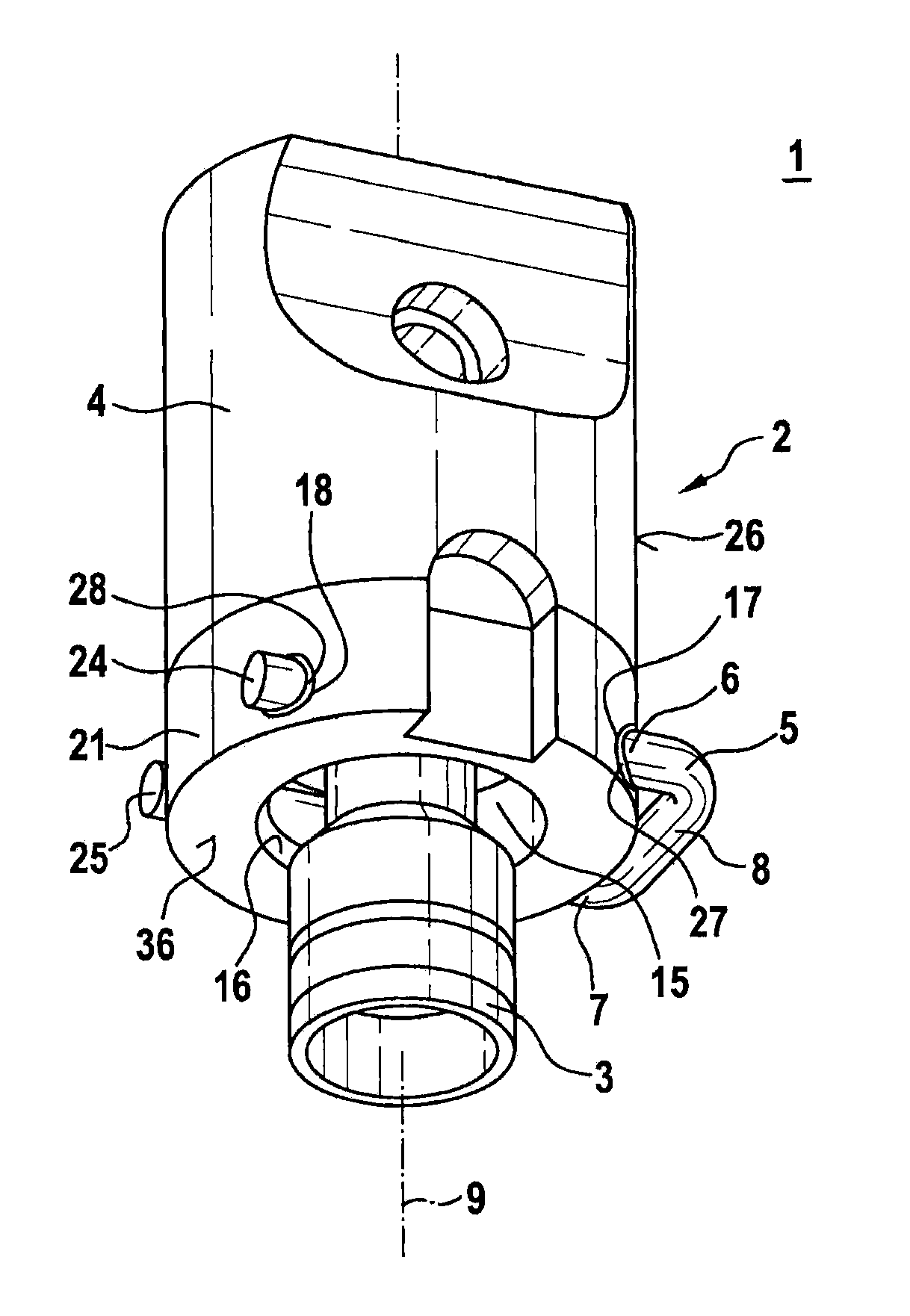
[0020]FIG. 1 shows a fuel injection system 1 having a connecting element 2 and a fuel connector 3 of a fuel injection valve corresponding to a first exemplary embodiment, in a partial schematic spatial representation. Fuel injection system 1 can be used in particular for high-pressure injection in internal combustion engines. Specifically, fuel injection system 1 can be used in mixture-compressing externally ignited internal combustion engines. Connecting element 2 is particularly suitable for such a fuel injection system 1.

[0021]Fuel injection system 1 preferably has a plurality of such connecting elements 2 in order to produce a connection to a plurality of fuel connectors 3 of a corresponding number of fuel injection valves. In this way, fuel injection system 1 can be specifically fashioned as a fuel injection system 1 for high-pressure injection in internal combustion engines, and fuel under high pressure can be apportioned to a plurality of fuel injection valves.

[0022]In this e...


PUM


Abstract

A connecting element connecting a fuel injection valve to a fuel-conducting component includes: a main body having a receptacle space into which a fuel connector of the fuel injection valve is introduced; and a fastening element. At least one opening is provided in a wall of the main body surrounding the receptacle space. The fastening element for fastening the fuel connector on the main body is brought into the receptacle space at least partly through the at least one opening. At least one elastic bearing element is provided, and the fastening element brought at least partly through the opening into the receptacle space is supported on the wall of the main body via the at least one elastic bearing element.

Description

BACKGROUND OF THE INVENTION[0001]1. Field of the Invention[0002]The present invention relates to a connecting element for fuel injection systems for connecting a fuel injection valve to a fuel-conducting component, and to a fuel injection system having such a connecting element. Specifically, the present invention relates to the area of fuel injection systems for mixture-compressing externally ignited internal combustion engines.[0003]2. Description of the Related Art[0004]From published German patent application document DE 10 2005 020 380 A1, a fuel injection device is known that is distinguished by a design that decouples sound. The known fuel injection device includes a fuel injection valve, a receptacle bore for the fuel injection valve in a cylinder head, and a fuel distributor line having a connecting piece into which the fuel injection valve is brought in partly overlapping fashion. In a possible embodiment, a connecting element is provided that on the one hand grasps a hold...

Claims


Application Information

Patent Timeline
Patent Type & Authority Patents(United States)
IPC IPC(8): F02M55/00F02M55/02F02M61/14F02M63/00F16L37/12F16L21/08
CPCF02M55/004F02M55/025F02M61/14F02M63/0012F16L21/08F16L37/1225F02M2200/855F02M2200/09F02M2200/803F02M2200/8023F02M2200/853
Inventor REINHARDT, WILHELMSCHEEF, VOLKERMAYER, MICHAELREHWALD, ANDREASHERRMANN, JANROGLER, PHILIPPGLASER, ANDREASHORST, HANS-GEORGRIEMER, MARTINKNORPP, MICHAELFISCHER, MICHAEL
Owner ROBERT BOSCH GMBH
Why Eureka
Try Eureka