
High dynamic range RF power monitor

a radio frequency and high dynamic range technology, applied in the direction of magnetic variable regulation, instruments, therapy, etc., can solve the problems of inability to investigate whether the scanner is operating safely within the sar guidelines, if performed at all, and the accuracy of scanner sar estimates is also questionabl

Active Publication Date: 2017-10-17
THE JOHN HOPKINS UNIV SCHOOL OF MEDICINE
View PDF26 Cites 2 Cited by
  • Summary
  • Abstract
  • Description
  • Claims
  • Application Information

AI Technical Summary

Benefits of technology

The system provides accurate, real-time measurements of RF power deposition and SAR, reducing the risk of RF burns and ensuring compliance with safety and regulatory standards by correcting the overestimation of SAR values reported by commercial scanners.

Problems solved by technology

Yet, rare as they may be compared to the total number of MRI scans performed, RF burns do occur, a fraction of which are reported to the FDA.16 In these cases, at least, a failure in scanner SAR monitoring has occurred.
Unfortunately, investigating whether the scanner is operating safely within SAR guidelines by means that are independent of the scanner, if performed at all, is not easy.17 The accuracy of scanner SAR estimates is also questionable in light of discrepancies with thermally-derived SAR measurements,17,18 especially during MRI safety-testing of interventional devices3, 18-20 and the lack of correlation between subjective heat perception by patients and scanner SAR.21
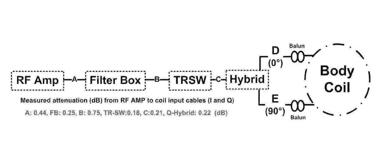
However, measuring the power delivered to the body is complicated by losses in the RF transmission chain, including the cables, switches, the quadrature-hybrid (Q-hybrid) and the MRI coil.23,24 These losses can vary over time, but are not routinely monitored.
However, they do not give accurate results for sequences using mixtures of high and low amplitudes or modulations, or long TR.

Method used


Image

  • High dynamic range RF power monitor
  • High dynamic range RF power monitor
  • High dynamic range RF power monitor

Examples


Embodiment Construction

[0023]Some embodiments of the current invention are discussed in detail below. In describing embodiments, specific terminology is employed for the sake of clarity. However, the invention is not intended to be limited to the specific terminology so selected. A person skilled in the relevant art will recognize that other equivalent components can be employed and other methods developed without departing from the broad concepts of the current invention. All references cited anywhere in this specification, including the Background and Detailed Description sections, are incorporated by reference as if each had been individually incorporated.

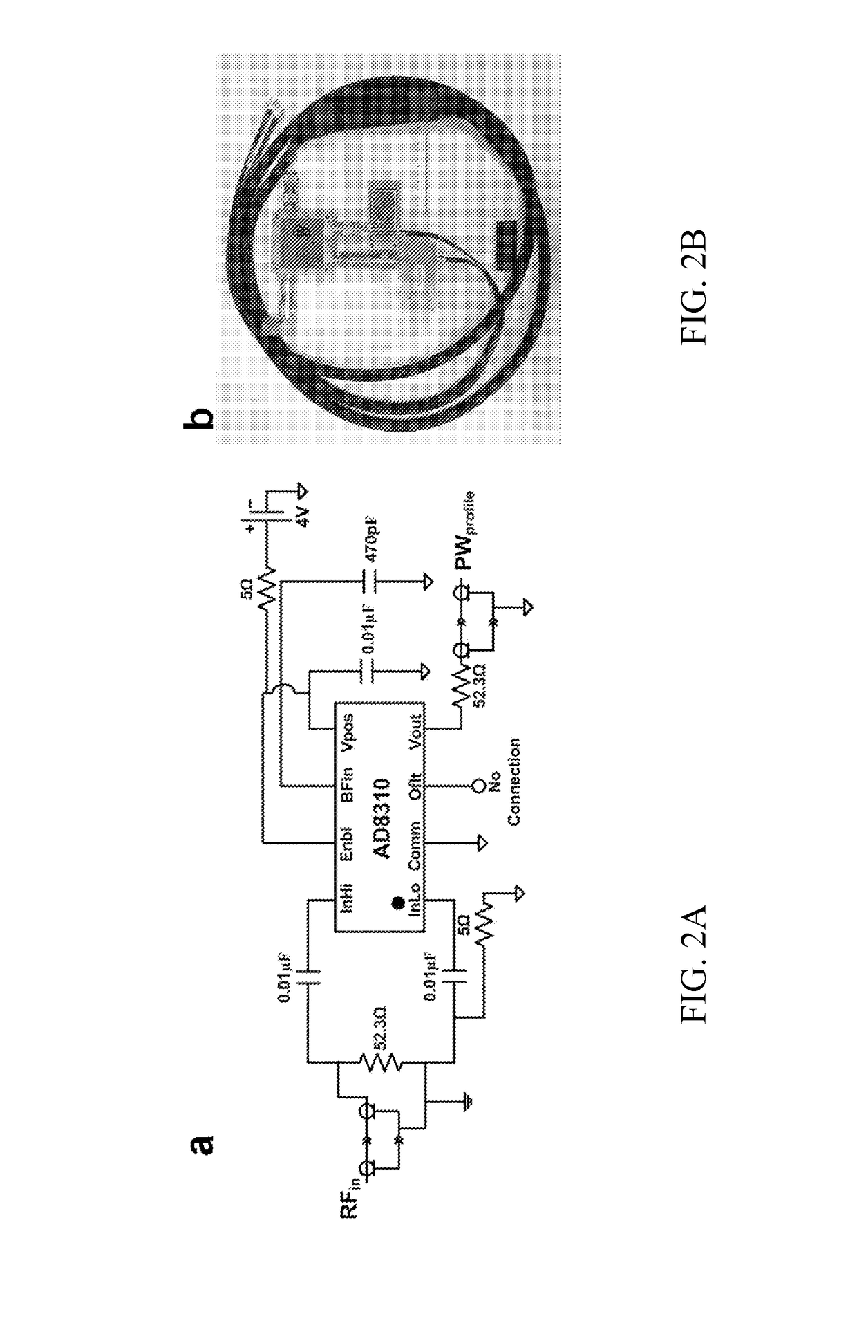
[0024]Some embodiments of the current invention provide a high-DR, MRI-compatible, power profiling system for measuring and recording RF power over a wide range of MRI scan conditions. The system is broadband up to 400 MHz, can be used to sample power for both local and whole-body power flow and, unlike commercial meters, has six channels and a buffer...


PUM


Abstract

A device with at least one channel for measuring high dynamic range, radio frequency (RF) power levels over broad-ranging duty cycles includes a power sensor circuit comprising at least one logarithmic amplifier; at least one directional RF coupler electrically connected to the at least one power sensor; at least one RF attenuator electrically connected to the at least one RF coupler; and at least one sampling circuit electrically connected to the at least one RF attenuator and the at least one RF coupler. The at least one sampling circuit performs analog-to-digital conversion of electrical signals received to provide digitals signals for measuring the RF power level in the at least one channel.

Description

CROSS-REFERENCE OF RELATED APPLICATION[0001]This is a national stage application under 35 U.S.C. §371 of PCT / US2012 / 030173 filed Mar. 22, 2012, the entire contents of which are incorporated herein by reference and this application claims priority to U.S. Provisional Application No. 61 / 466,194 filed Mar. 22, 2011, the entire contents of which are hereby incorporated by reference.[0002]This invention was made with government support under R01EB007829 awarded by the National Institutes of Health. The government has certain rights in the invention.BACKGROUND[0003]1. Field of Invention[0004]The field of the currently claimed embodiments of this invention relates to high dynamic range (DR) radio frequency (RF) power monitoring devices and methods.[0005]2. Discussion of Related Art[0006]Accurate knowledge of the RF specific absorption rate (SAR) in the body during magnetic resonance imaging (MRI) scans is important for patient safety and compliance with limits mandated by the Food and Drug...

Claims


Application Information

Patent Timeline
Patent Type & Authority Patents(United States)
IPC IPC(8): G01R27/32G01R21/00G01R33/36A61N1/00G06F1/00G01R1/00G01R21/10G01R33/28
CPCG01R27/32G01R21/00G01R33/3614A61N1/00G01R1/00G01R21/10G01R33/288G06F1/00G06F2101/00
Inventor BOTTOMLEY, PAUL A.EDELSTEIN, WILLIAMEL-SHARKAWY, ABDEL-MONEM M.QIAN, DI
Owner THE JOHN HOPKINS UNIV SCHOOL OF MEDICINE
Learn More