Wireless measuring system and method for measurement of a device under test with an antenna-array, considering maximum gain direction of the antenna array

a technology of antenna array and measurement system, which is applied in the direction of spatial transmit diversity, transmission, network topologies, etc., can solve the problems of not being applicable to the device under test, the interface may no longer be effective for performing antenna measurements, and the measuring system according, so as to reduce the rotation amount, efficiently determine the actual maximum gain direction of the antenna array, and effectively determine the quality of the antenna array adjustment

Active Publication Date: 2017-10-03
ROHDE & SCHWARZ GMBH & CO KG
View PDF17 Cites 2 Cited by
  • Summary
  • Abstract
  • Description
  • Claims
  • Application Information

AI Technical Summary

Benefits of technology

[0012]According to one embodiment, the control unit is adapted to set an antenna characteristic of the antenna-array of the device under test, such as adjusting a set maximum gain direction of the antenna-array. By way of example, the control unit is adapted to instruct the device under test mount to rotate the communication device under test compensating for the set maximum gain direction of the antenna-array, so that the set maximum gain direction of the antenna-array meets a direction of the measuring antenna regarding the device under test. By way of further example, the control unit is adapted to determine an actual maximum gain direction of the antenna-array by iteratively instructing the device under test mount to rotate the device under test to determine a present gain of the antenna-array, and to determining the actual maximum gain direction as a rotation direction of the device under test mount of maximal gain. The measuring system thereby facilitates an accurate determination of the function of setting the antenna characteristics and the maximum gain direction of the antenna-array with a low-complexity hardware implementation.
[0018]In accordance with further example embodiments, a measuring method for performing measurements on a communication device under test having an antenna-array, is provided. The measuring method comprises positioning at least one measuring antenna in a fixed location and orientation regarding a device under test mount and positioning the communication device under test in the device under test mount. The measuring method further comprises setting an antenna characteristic of the antenna-array of the communication device under test thereby adjusting a set maximum gain direction of the antenna-array. By way of example, the method comprises the step of rotating the communication device under test using the device under test mount and compensating for the set maximum gain direction of the antenna-array, so that the set maximum gain direction of the antenna-array meets a direction of the measuring antenna regarding the device under test. By way of further example, the method comprises determining an actual maximum gain direction of the antenna-array by iteratively rotating the communication device under test using the device under test mount, determining a present gain of the antenna-array and determining the actual maximum gain direction as a rotation direction of the device under test mount of maximal gain. Thereby, a very efficient determining of the characteristics of the device under test is possible.

Problems solved by technology

When using highly integrated active antennas, however, such an interface may no longer be effective for performing antenna measurements.
The measuring system according to US20130093447A1 though is not applicable to devices under test that use antenna-arrays, beamforming, antenna diagrams and maximum gain directions of an antenna array.
It is therefore not possible to perform accurate measurements on future generations of devices under test using the measuring system of this publication.

Method used


Image

  • Wireless measuring system and method for measurement of a device under test with an antenna-array, considering maximum gain direction of the antenna array
  • Wireless measuring system and method for measurement of a device under test with an antenna-array, considering maximum gain direction of the antenna array
  • Wireless measuring system and method for measurement of a device under test with an antenna-array, considering maximum gain direction of the antenna array

Examples


Embodiment Construction

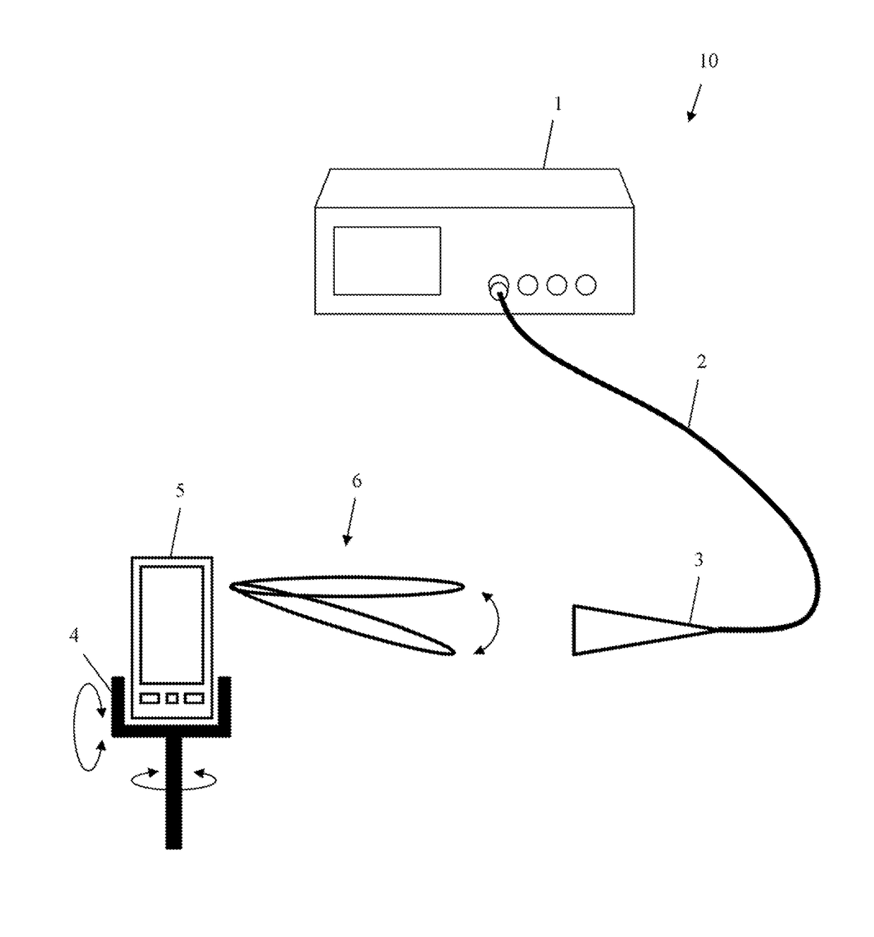
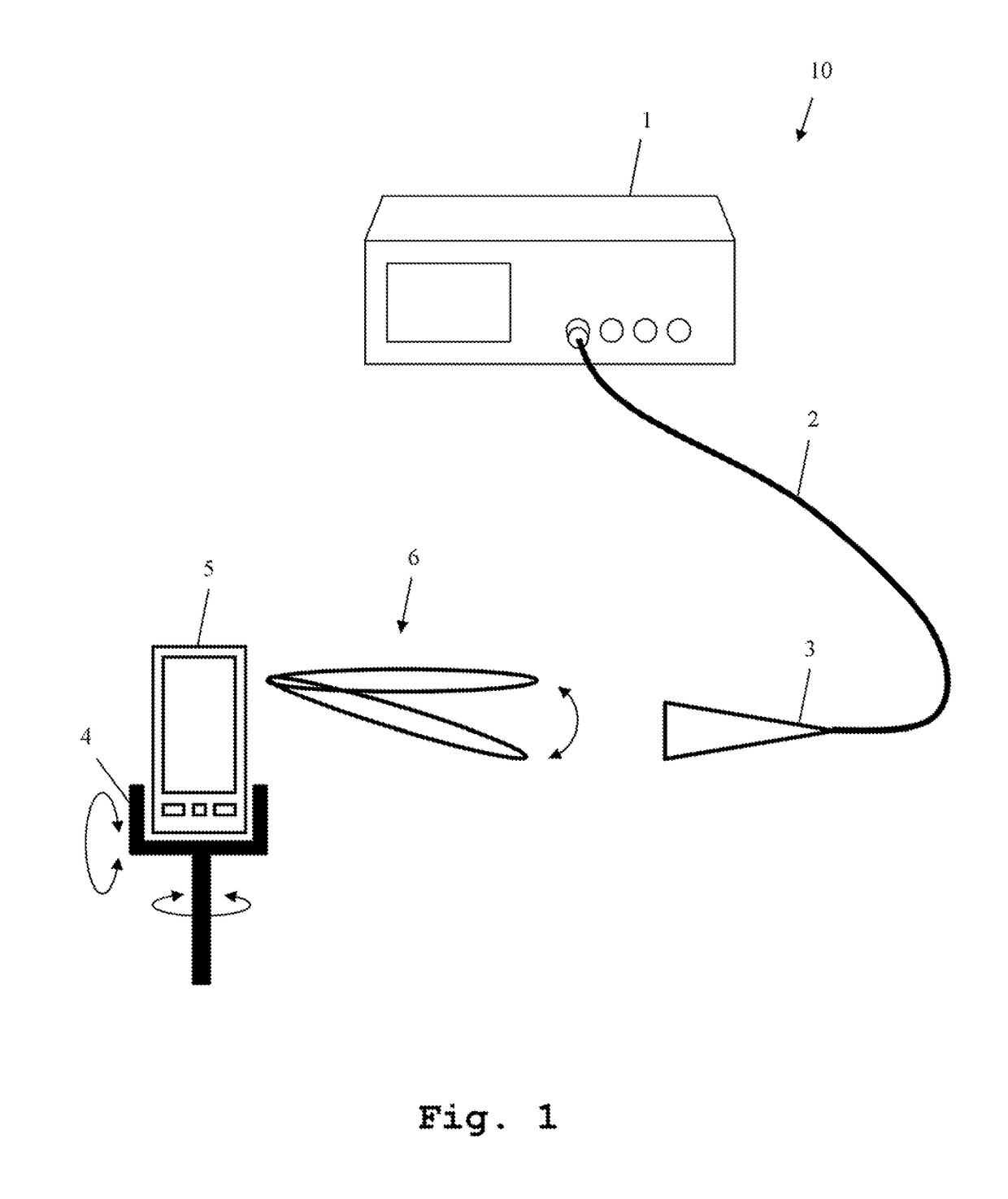
[0030]FIG. 1 shows a block diagram of a three dimensional overview of a measuring system, in accordance with example embodiments of the present invention. The measuring system 10 comprises a measuring device 1, a measuring antenna 3 connected to the measuring device 1 by a coaxial cable 2 and a device under test mount 4. The device under test mount 4 holds a communication device under test 5. The device under test 5 comprises an antenna-array (which is not depicted in the figure as an external antenna of the device 5). By adjusting the antenna characteristic of the antenna-array, different antenna characteristics, and thereby maximum gain directions 6, of the antenna-array can be set.

[0031]When performing a transmission measurement, the device under test 5 transmits a measuring signal using a presently set antenna characteristic, and thereby a presently set maximum gain direction 6. The measuring signal is received by the measuring antenna 3 and handed on to the measuring device 1 v...


PUM


Abstract

A measuring system for measuring a communications device comprising an antenna-array. The measuring system comprises a controller, a measuring device, a measuring antenna and a device mount. The measuring device performs measurements with regard to the communications device. The device mount rotates the communications device about at least one axis. The controller sets a maximum gain direction of the antenna-array. The controller (i) controls the device mount to rotate the communications device, compensating for the set maximum gain direction, until the set maximum gain direction meets a direction of the measuring antenna with respect to the communications device, and (ii) determines an actual maximum gain direction of the antenna-array by iteratively rotating the communications device and determining a respective gain for each iteration, and determines the actual maximum gain direction as a rotation of the device mount that corresponds to the iteration of maximal gain.

Description

RELATED APPLICATIONS[0001]This application claims priority to European patent application EP 15 170 968.0, filed Jun. 8, 2015, which is incorporated herein by reference in its entirety.FIELD[0002]The invention relates to a measuring system and method for communication devices comprising antenna-arrays, especially antenna-arrays used for beamforming.BACKGROUND[0003]Beyond the current long term evolution LTE technology, and first significant improvements (LTE-A), the next generation mobile communications technology 5G is imminent. Regarding 5G, a move to even higher frequencies and larger bandwidths are to be expected. Although the exact frequency bands are not yet specified, frequencies up to 75 GHz are in discussion. For reaching sufficient ranges using these frequencies, the antenna technology is a core aspect. High antenna gains are necessary. In order to reach such high antenna gains, the use of antennas with a large number of radiating elements, especially phased-array antennas ...

Claims


Application Information

Patent Timeline
Patent Type & Authority Patents(United States)
IPC IPC(8): H04W24/06H04B7/06H04B17/12H04B17/21H04B17/10H04W84/04
CPCH04W24/06H04B17/12H04B7/0617H04B17/21H04B17/102H04W84/042
Inventor PAULY, ANDREASSTEFFENS, JOHANNESKOTTKAMP, MEIK
Owner ROHDE & SCHWARZ GMBH & CO KG
Why Eureka
Try Eureka