
Guide vane assembly

a technology of guide vane and assembly, which is applied in the direction of machines/engines, stators, liquid fuel engines, etc., can solve the problems of inability to adapt to the fixing arrangement of composite ogvs, the inability of conventional manufacturing/assembling methods to use composite ogvs, and the inability to bolt straight through composite materials. to achieve the effect of improving the impact toughness of the componen

Active Publication Date: 2017-10-03
ROLLS ROYCE PLC
View PDF33 Cites 4 Cited by
  • Summary
  • Abstract
  • Description
  • Claims
  • Application Information

AI Technical Summary

Benefits of technology

This patent describes a way to attach composite aerofoil members to an engine in a simple and strong way. The arrangement includes a vane assembly attachment web that can be easily manufactured and assembled. The aerofoil members also have a protective coating that can withstand erosion during use. The outer surface of the assembly can be formed by a glass fibre skin, which improves impact toughness. The aerofoil members may also have a protective layer on the leading edge. This arrangement allows for easy replacement of damaged guide vane assemblies, reducing costs and simplifying the repair process.

Problems solved by technology

However, conventional approaches to manufacturing / assembling an OGV stage may not be appropriate when using composite OGVs.
Composite materials may not be well suited to such fixing arrangements.
For example, bolting straight through composite material may be expensive / time-consuming and / or may significantly weaken the component.
This may compromise the design and / or result in shorter life spans.
For example, in a flange-type fixing, bolting through flanges can introduce potential weak points in any resin rich areas and may add manufacturing complexity.
Furthermore, drilling fixing holes through any loaded area of a composite structure is not desirable as it may introduce discontinuities to some of the fibres.
Using a dovetail-type fixing may require a rapid build-up of thickness of the composite material, making the manufacturing process more complex and potentially introducing weakness at ply drop interfaces.

Method used


Image

  • Guide vane assembly
  • Guide vane assembly
  • Guide vane assembly

Examples


Embodiment Construction

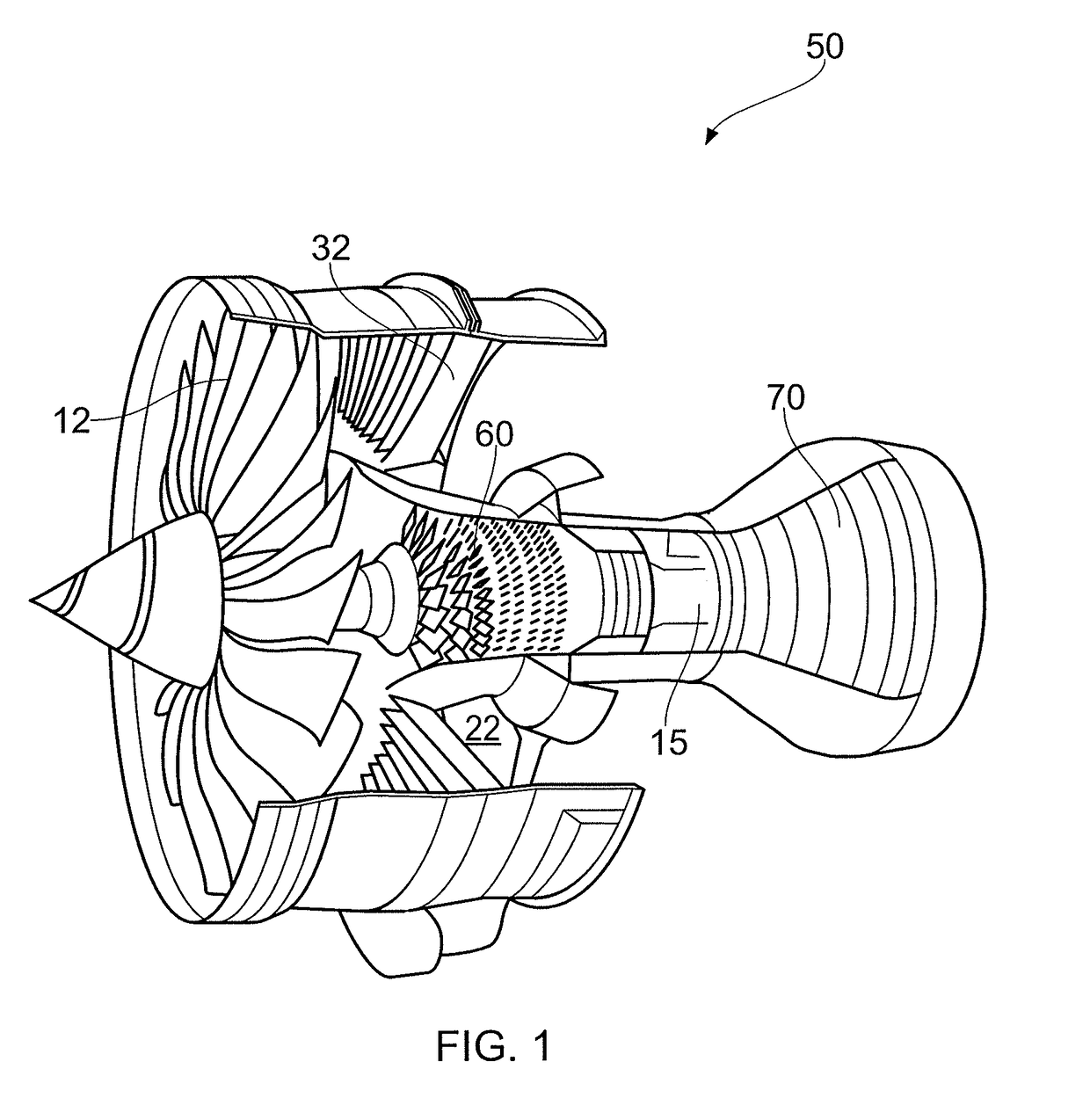
[0068]With reference to FIG. 4, a ducted fan gas turbine engine generally indicated at 10 has a principal and rotational axis X-X. The engine 10 comprises, in axial flow series, an air intake 11, a propulsive fan 12, an intermediate pressure compressor 13, a high-pressure compressor 14, combustion equipment 15, a high-pressure turbine 16, and intermediate pressure turbine 17, a low-pressure turbine 18 and a core engine exhaust nozzle 19. The engine also has a bypass duct 22 and a bypass exhaust nozzle 23.

[0069]The gas turbine engine 10 works in a conventional manner so that air entering the intake 11 is accelerated by the fan 12 to produce two air flows: a first air flow A into the intermediate pressure compressor 13 and a second air flow B which passes through the bypass duct 22 to provide propulsive thrust. The intermediate pressure compressor 13 compresses the air flow A directed into it before delivering that air to the high pressure compressor 14 where further compression takes...


PUM


Abstract

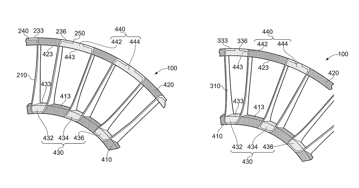
A guide vane assembly for a stator vane stage comprises at least two aerofoil members joined together using a vane assembly attachment web. The vane assembly attachment web may be provided at the inner and / or outer radius of the aerofoil members. The vane assembly attachment web allows the guide vane assembly to be attached to an inner and / or outer attachment ring, thereby forming a stator vane stage. Such an arrangement may allow composite fiber reinforced guide vane assemblies to be readily assembled together to form stator vane stages. Stator vane stages that comprise such composite fiber reinforced guide vane assemblies may be lighter than conventional metallic stator vane stages.

Description

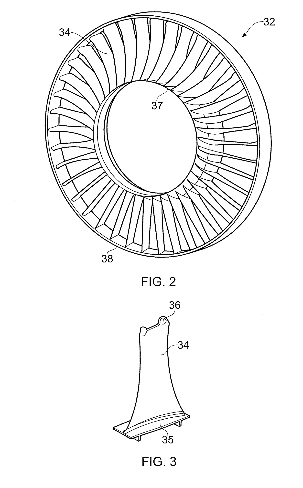
CROSS-REFERENCE TO RELATED APPLICATIONS[0001]This application is based upon and claims the benefit of priority from British Patent Application Number 1215906.7, filed 6 Sep. 2012, the entire contents of which are incorporated by reference.BACKGROUND OF THE INVENTION[0002]1. Field of the Invention[0003]The present invention relates to a guide vane assembly for a gas turbine engine. In particular, aspects of the invention relate to a composite guide vane assembly and arrangements for attaching composite guide vane assemblies to a gas turbine engine.[0004]2. Description of the Related Art[0005]An axially rotating gas turbine engine comprises a number of rotor stages and a number of stator stages, each comprising aerofoil members mounted around an engine axis. The rotor stages are arranged such that, in use, the aerofoil members rotate around the engine axis. The stator stages are arranged such that, in use, the aerofoil members are fixed in position around the engine axis. Conventional...

Claims


Application Information

Patent Timeline
Patent Type & Authority Patents(United States)
IPC IPC(8): F03B3/18F01D9/04F04D29/02F01D5/28F04D29/64F01D25/24F04D29/54
CPCF01D9/042F01D5/282F01D9/041F01D25/246F04D29/023F04D29/542F04D29/544F04D29/644F05D2230/50F05D2230/64F05D2300/603F05D2300/6034Y02T50/60
Inventor DRANE, ANDREW JAMES
Owner ROLLS ROYCE PLC
Learn More