
LED tube lamp with operating modes compatible with electrical ballasts

a technology of operating modes and led tubes, applied in the field of illumination devices, can solve the problems of user electrical shock, wires may be easily damaged and even broken, and the led tube lamp cannot be used, so as to facilitate the led tube lamp and improve the stability of power supply

Active Publication Date: 2017-09-26
JIAXING SUPER LIGHTING ELECTRIC APPLIANCE
View PDF54 Cites 40 Cited by
  • Summary
  • Abstract
  • Description
  • Claims
  • Application Information

AI Technical Summary

Benefits of technology

The solution provides enhanced safety by preventing electrical shock and improves compatibility with electronic ballasts, ensuring stable and efficient lighting operations by allowing for flexible installation and adaptive current regulation.

Problems solved by technology

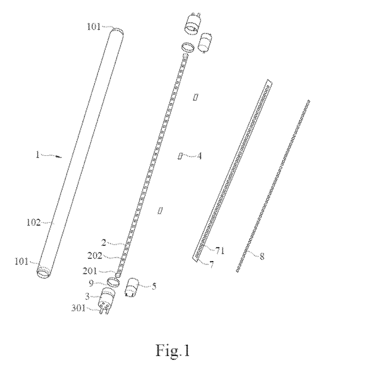
First, the typical circuit board is rigid and allows the entire lamp tube to maintain a straight tube configuration when the lamp tube is partially ruptured or broken, and this gives the user a false impression that the LED tube lamp remains usable and is likely to cause the user to be electrically shocked upon handling or installation of the LED tube lamp.
Second, the rigid circuit board is typically electrically connected with the end caps by way of wire bonding, in which the wires may be easily damaged and even broken due to any move during manufacturing, transportation, and usage of the LED tube lamp and therefore may disable the LED tube lamp.
Further, circuit design of current LED tube lamps mostly doesn't provide suitable solutions for complying with relevant certification standards and for better compatibility with the driving structure using an electronic ballast originally for a fluorescent lamp.
However, there are a considerable number of electronic components in an LED tube lamp, and therefore consideration of the impacts caused by the layout (structure) of the electronic components is important, resulting in difficulties in complying with such standards.
Therefore, using an LED tube lamp with an electronic ballast impacts the resonant circuit design of the electronic ballast, which may cause a compatibility problem.
Generally, a programmed-start ballast will detect the presence of a filament in a fluorescent lamp, but traditional LED driving circuits cannot support the detection and may cause a failure of the filament detection and thus failure of the starting of the LED tube lamp.
Further, electronic ballast is in effect a current source, and when it acts as a power supply of a DC-to-DC converter circuit in an LED tube lamp, problems of overvoltage and overcurrent or undervoltage and undercurrent are likely to occur, resulting in damaging of electronic components in the LED tube lamp or unstable provision of lighting by the LED tube lamp.
Since the voltages and frequency spectrums of these types of signals differ significantly, simply performing a rectification to produce the required DC driving signal in an LED tube lamp is typically not competent at achieving the LED tube lamp's compatibility with traditional driving systems of a fluorescent lamp.
Conventional fluorescent lamps and LED lamps are typically not equipped with advanced abilities both to regulate their electrical currents for better qualities or functions and to be compatible with various types of ballasts avoiding typical needs to find a suitable lamp when the fluorescent or LED lamp is not compatible with a present type of ballast.

Method used


Image

  • LED tube lamp with operating modes compatible with electrical ballasts
  • LED tube lamp with operating modes compatible with electrical ballasts
  • LED tube lamp with operating modes compatible with electrical ballasts

Examples


Embodiment Construction

[0074]The present disclosure provides a novel LED tube lamp, and also provides some features that can be used in LED lamps that are not LED tube lamps. The present disclosure will now be described in the following embodiments with reference to the drawings. The following descriptions of various implementations are presented herein for purpose of illustration and giving examples only. This invention is not intended to be exhaustive or to be limited to the precise form disclosed. These example embodiments are just that—examples—and many implementations and variations are possible that do not require the details provided herein. It should also be emphasized that the disclosure provides details of alternative examples, but such listing of alternatives is not exhaustive. Furthermore, any consistency of detail between various examples should not be interpreted as requiring such detail—it is impracticable to list every possible variation for every feature described herein. The language of ...


PUM


Abstract

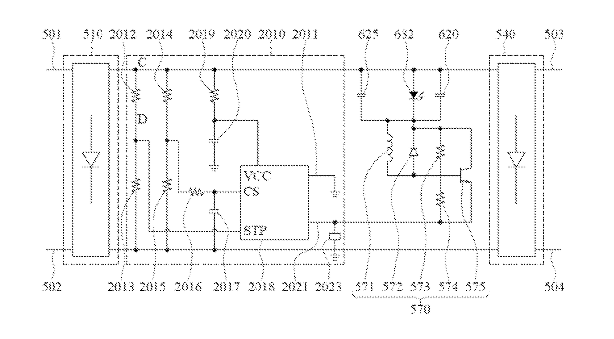
An LED tube lamp having an LED unit is disclosed. The LED tube lamp includes a control circuit that selectively determines whether to perform a first mode or a second mode of lighting operation according to a state of a property of an external driving signal and a switching circuit coupled to the control circuit and the LED unit. When the control circuit determines to perform the first mode of lighting operation, the control circuit controls the second circuit in a manner such that the switching circuit maintains its on state to allow continual current to flow through the LED unit, until the external driving signal is disconnected from the LED tube lamp, and when the control circuit determines to perform the second mode of lighting operation, the control circuit controls the switching circuit in a manner to regulate the continuity of current to flow through the LED unit by alternately turning on and off the switching circuit.

Description

[0001]This application is a continuation-in-part application of U.S. patent application Ser. No. 15 / 211,813, filed Jul. 15, 2016, which is a continuation-in-part application of U.S. patent application Ser. No. 15 / 150,458, filed May 10, 2016, which is a continuation-in-part application of U.S. patent application Ser. No. 14 / 865,387, filed Sep. 25, 2015 and is a continuation-in-part application of U.S. patent application Ser. No. 14 / 699,138, filed Apr. 29, 2015, the contents of which four previous applications are incorporated herein by reference in their entirety, and this application is a continuation-in-part application of U.S. patent application Ser. No. 15 / 211,783, filed Jul. 15, 2016, the contents of which are incorporated herein by reference in their entirety and which is a continuation-in-part application of U.S. patent application Ser. No. 15 / 087,088, filed Mar. 31, 2016, which is a continuation-in-part application of U.S. patent application Ser. No. 14 / 865,387, filed Sep. 25...

Claims


Application Information

Patent Timeline
Patent Type & Authority Patents(United States)
IPC IPC(8): H05B37/00H05B33/08H05B41/00F21K9/27H05B44/00
CPCH05B33/0887H05B33/0809F21K9/27F21K9/278H05B45/50H05B45/3725H05B47/25H05B47/24H05B45/59
Inventor XIONG, AIMINGLIU, XINTONGWU, XIAOJIACHEN, JUNREN
Owner JIAXING SUPER LIGHTING ELECTRIC APPLIANCE
Learn More