
Sterile liquid pump with single use elements

a single-use, liquid pump technology, applied in the direction of positive displacement liquid engine, piston pump, liquid fuel engine, etc., can solve the problems of not fully transitioning into the single-use paradigm, the cost of maintaining the cleanliness of the pumping equipment, the validation and maintenance of the system, and the cost of pumping equipment cleaning and sterilization utilities

Active Publication Date: 2017-09-19
THE SINGLE USE PUMP CO LLC
View PDF10 Cites 2 Cited by
  • Summary
  • Abstract
  • Description
  • Claims
  • Application Information

AI Technical Summary

Benefits of technology

The solution provides a cost-effective, flexible, and highly accurate pumping system that maintains sterility and purity, offering ultra-low shear, high turndown ratios, and precise control, reducing downtime and maintenance costs while ensuring the integrity of sensitive liquids.

Problems solved by technology

One common issue in such applications is the need to maintain the cleanliness of the pumping equipment, always with an eye on the cost and downtime needed to maintain such equipment.
Experience in the industry has demonstrated that cleaning and sterilization utilities, as well as validation and maintenance of the systems, are found to be more expensive than operating with single use equipment.
Such systems have not yet been fully transitioned into the single use paradigm for this reason alone.
This approach drives up the cost of the liner and creates material recycling issues with respect to the rare earth materials, such as neodymium, used in the magnet.
Shipping liners with impellers inside is a packaging challenge as well.
Liners are often found to leak from where the impeller has vibrated against the film.

Method used


Image

  • Sterile liquid pump with single use elements
  • Sterile liquid pump with single use elements
  • Sterile liquid pump with single use elements

Examples


Embodiment Construction

[0040]Illustrative embodiments and exemplary applications will now be described with reference to the accompanying drawings to disclose the advantageous teachings of the present invention.

[0041]While the present invention is described herein with reference to illustrative embodiments for particular applications, it should be understood that the invention is not limited thereto. Those having ordinary skill in the art and access to the teachings provided herein will recognize additional modifications, applications, and embodiments within the scope hereof, and additional fields in which the present invention would be of significant utility. The apparatus and system components and method steps have been represented where appropriate by conventional symbols in the drawings, showing only those specific details that are pertinent to understanding the present invention so as not to obscure the disclosure with details that will be readily apparent to those of ordinary skill in the art having...


PUM


Abstract

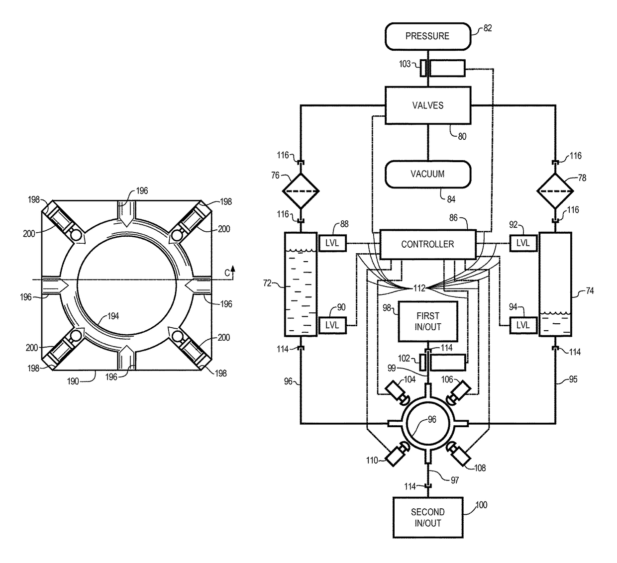
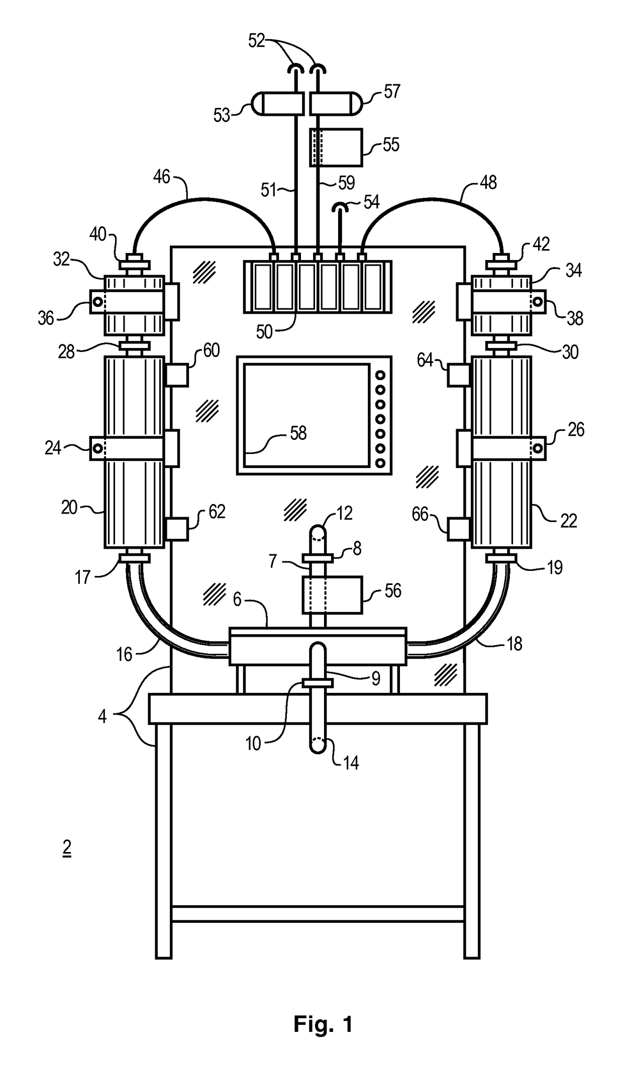
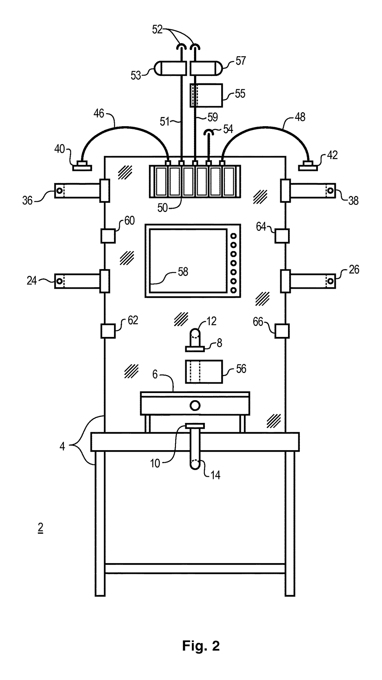
A sterile liquid pump, having replaceable single use components, with a first and second chamber, and a gas valve assembly to selectively communicate gas pressure and vacuum with the chambers, and a resilient tubing liquid manifold loop with a sequence of four ports located within a manifold receiver that supports four pinch actuators aligned to engage and selectively pinch-off flow through the manifold between adjacent pairs ports, and, a controller that operates the valve assembly to alternatingly couple pressure and vacuum to the pump chambers, and that also operates to alternatingly actuate pairs of the pinch actuators to sequentially pump fluid from pump chambers under gas pressure, and through an opposing pair of ports in the resilient tubing manifold.

Description

BACKGROUND OF THE INVENTION[0001]Field of the Invention[0002]The present invention relates to liquid pumps. More particularly, the present invention relates to gas pressure and vacuum driven liquid pumps suitable for high purity and sterile liquid pumping applications.[0003]Description of the Related Art[0004]In many critical applications, there is a need for liquid transfer where the transferred liquid must be very carefully handled so as not to compromise the purity, physical, chemical, biological, or pharmaceutical characteristics of the liquid. One common issue in such applications is the need to maintain the cleanliness of the pumping equipment, always with an eye on the cost and downtime needed to maintain such equipment. By way of example, the biopharmaceutical industry is shifting to more single use equipment to reduce cost and increase flexibility in the manufacturing processes. Experience in the industry has demonstrated that cleaning and sterilization utilities, as well a...

Claims


Application Information

Patent Timeline
Patent Type & Authority Patents(United States)
IPC IPC(8): F04B43/08F04F1/02B01F15/02F04B9/12F04B9/129F04B53/16B67D1/10
CPCF04B43/082B01F15/0243B67D1/108F04B9/1207F04B9/1295F04B53/16F04F1/02B01F35/7176
Inventor COX, C. ANTHONYAUSTIN, JAMES A.
Owner THE SINGLE USE PUMP CO LLC
Learn More