
Method for creating a resonator

a resonator and resonator technology, applied in the field of creating resonators, can solve the problem of not being able to produce hollow parts with straight sides or walls

Active Publication Date: 2017-09-05
THE SWATCH GRP RES & DEVELONMENT LTD
View PDF22 Cites 0 Cited by
  • Summary
  • Abstract
  • Description
  • Claims
  • Application Information

AI Technical Summary

Benefits of technology

The present invention allows for the creation of complex inner recesses using a laser-transparent material. The laser can aim at any point on the surface or underneath the surface of the resonator, and the material used is selective so that the chemical etch that follows is only performed on the material that has undergone modification by the laser. The method is applicable to different substrate materials, such as single crystal or polycrystalline material. Overall, this technique provides a highly precise and efficient way to create inner recesses in structures.

Problems solved by technology

A first drawback of this chemical etching technique is that it cannot produce hollow portions with straight sides or walls.

Method used


Image

  • Method for creating a resonator
  • Method for creating a resonator
  • Method for creating a resonator

Examples


Embodiment Construction

[0067]FIGS. 4 and 5 show schematic views of a component according to the present invention.

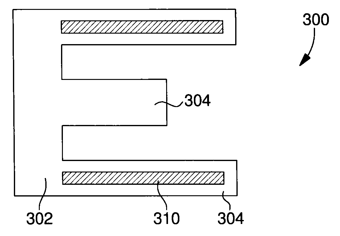
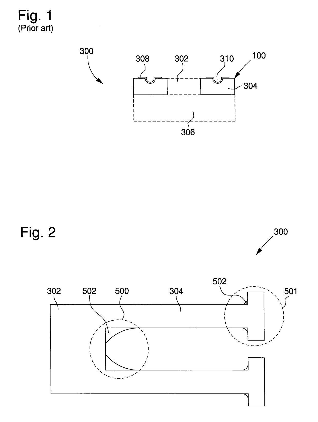
[0068]The component 101, manufactured in accordance with the method of the present invention, is a resonator 300. A conventional resonator, shown in FIG. 1, includes a body 100 used in deformation. This body 100 takes the form of a base 302 placed on a support base 306 and from which extend at least two parallel arms 304. These two parallel arms 304 carry metallisations which form, on the arms, two groups of electrodes 308 for subjecting them to electrical fields and making them vibrate. Resonator 300 further includes, on base 302, connection pads 309, respectively connected to groups of electrodes 308 as seen in FIG. 5. Each arm 304 includes an upper surface 314 and a lower surface 316. The typical dimensions of this type of resonator 300 are: length 1 mm, width 0.1 mm, thickness 0.1 mm. The resonator also has sides or walls 311.

[0069]In order to improve the characteristics of resonator 300, ...


PUM

PropertyMeasurementUnit
thicknessaaaaaaaaaa
widthaaaaaaaaaa
lengthaaaaaaaaaa

Abstract

A method for manufacturing a resonator in a substrate, including: a) modifying a structure of at least one region of the substrate to make the at least one region more selective; b) etching the at least one region to selectively manufacture the resonator.

Description

CROSS-REFERENCE TO RELATED APPLICATIONS[0001]This is a National Phase Application in the United States of International Patent Application PCT / EP2012 / 076498 filed Dec. 20, 2012 which claims priority on European patent Application No. 11195420.2 filed Dec. 22, 2011. The entire disclosures of the above patent applications are hereby incorporated by reference.[0002]The invention concerns a resonator including a body used in deformation as a spiral resonator or a tuning fork.BACKGROUND OF THE INVENTION[0003]It is known from the prior art that some microtechnical parts made of single crystal or polycrystalline materials, such as resonators, are made by etching. This technique consists in taking the substrate to be etched and depositing a layer of photosensitive resin on top. A mask is placed on the resin and the whole assembly is exposed to light so that the photosensitive resin structure exposed to light is modified. This modified resin is eliminated by the action of a chemical element ...

Claims


Application Information

Patent Timeline
Patent Type & Authority Patents(United States)
IPC IPC(8): B44C1/22H03H9/19B81C1/00G04C3/12G04F5/06G04G17/02G04B17/06G04B17/34B23K26/00F21V17/02H01L41/047H01L41/332H03H9/215H10N30/082H10N30/87
CPCH03H9/19B23K26/0057B81C1/00595F21V17/02G04B17/066G04B17/345G04C3/12G04F5/063G04G17/02H01L41/0475H01L41/332H03H9/215B81B2201/0271B81B2203/0118B81C2201/0143C04B35/10C04B35/62605C04B2235/95B23K26/53B81B2203/019C04B35/48C04B35/5611C04B35/565C04B35/584C04B35/628C04B35/62836C04B35/62865C04B35/62871C04B35/62878C04B35/62884C04B2235/5436C04B41/0027H10N30/082H10N30/875
Inventor HESSLER, THIERRYDALLA PIAZZA, SILVIO
Owner THE SWATCH GRP RES & DEVELONMENT LTD
Learn More