
Chemical carbon dioxide gas generator

a carbon dioxide and gas generator technology, applied in the field of applied chemistry, can solve the problems of limiting the applicability of such gas generators to systems that can withstand such high temperatures, forming relatively large quantities of undesired side-products, and a relative complex structure of these units

Active Publication Date: 2017-08-29
NEDERLANDSE ORG VOOR TOEGEPAST-NATUURWETENSCHAPPELIJK ONDERZOEK (TNO)
View PDF19 Cites 0 Cited by
  • Summary
  • Abstract
  • Description
  • Claims
  • Application Information

AI Technical Summary

Benefits of technology

The invention provides a charge composition that has low toxicity. This means that the gas generator used in the invention is safe and not harmful to the environment or living organisms.

Problems solved by technology

In RU 2108282 it is observed that one of the drawbacks of the hitherto known art as cited above is the relatively complicated structure of these units.
Another drawback is that the known gas generators did not allow or provide for the gases to be cooled below 150° C., which limits the applicability of such gas generators to systems that can withstand such high temperatures.
Further disadvantages include the formation of relatively large quantities of undesired side-products, e.g. carbon monoxide (CO) or nitrogen oxides, a large mass and large size of the generator.
For nitrogen gas generators RU 2108282 has the drawback of a reactive slag remaining after usage.
This reactive slag requires controlled dismantling of the used gas generator, which make them less suitable for consumer products.
WO 03 / 009899 relates to a cool oxygen chemical gas generator, which allows the production of oxygen gas at a temperature below 50° C. Although this generator may serve as an alternative to nitrogen in some applications, the reactivity of oxygen can be disadvantageous or make the generated gas unsuitable for a specific purpose.
In general, the gas cannot be used in fire extinguisher applications, and may contribute to oxidation reactions, e.g. corrosion of materials that come in contact with oxygen.

Method used


Image

  • Chemical carbon dioxide gas generator
  • Chemical carbon dioxide gas generator

Examples


examples

[0096]Charges consisting of magnesium carbonate, oxidiser, fuel and binder were made as follows: after weighing the dry powders have been extensively mixed. The water soluted binder was added with the right amount of moisture and again were extensively mixed in order to obtain a homogenised mixture. The mixture was than granulated over a sieve and put in a mould and compressed in several steps to the required overall porosity. The moulds with the wet porous charges were dried in an oven according to an optimized drying profile in a temperature range between ambient and 150° C. Afterward the charges were taken out of the moulds and visually inspected.

[0097]In the following table, compositions are given of the tested charges, as well as the used gas treatment units (in the gas generator, downstream of the charge). The total weight for the charges was about 100 g.

[0098]

othergasMgCO3NaClO3fuel (C)K2SiO3chargetreatmentEx #wt. %wt. %wt. %wt. %componentsunit1533557—146 g sand*2543547—146 g...


PUM


Abstract

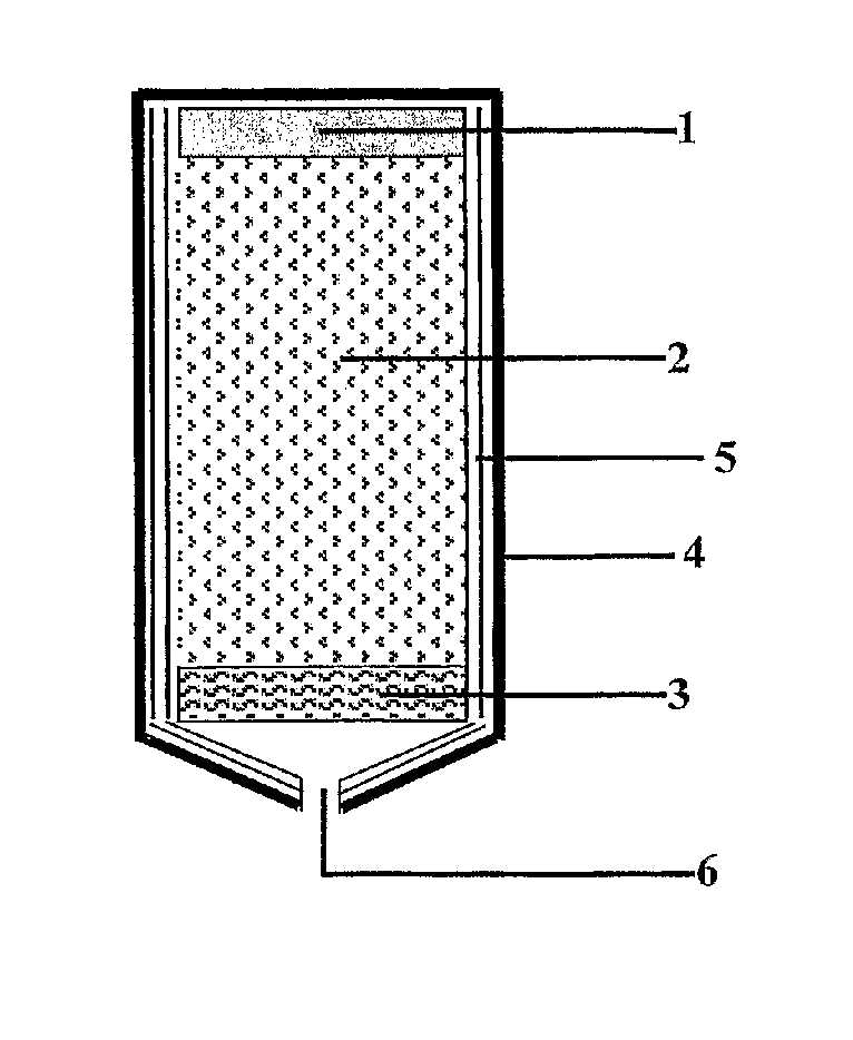
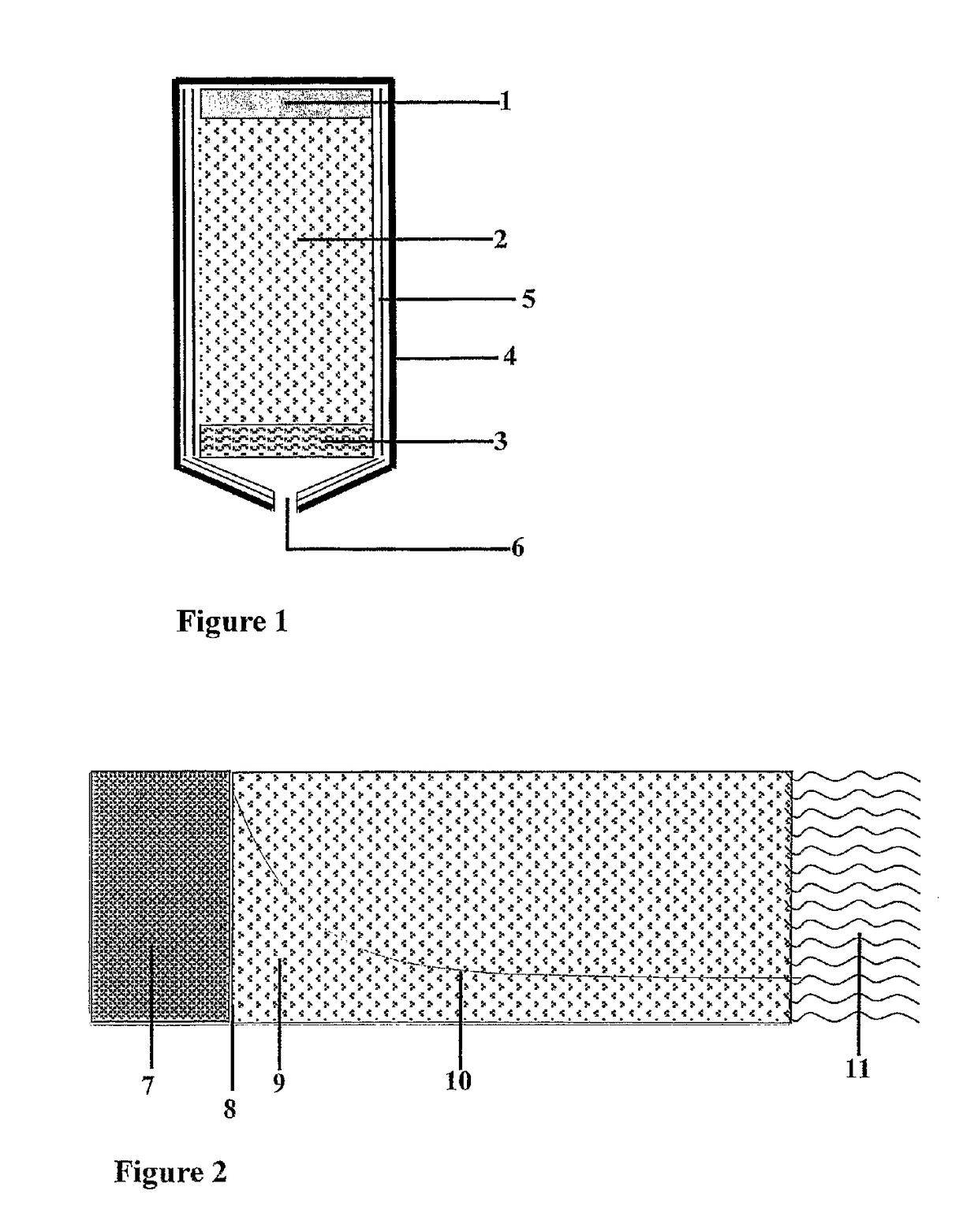
A chemical carbon dioxide gas generator comprising:a charge housing;a carbon dioxide gas penetrable charge, contained in the said housing, the charge comprisinga) 40-60 wt. % of a substance which upon decomposition generates carbon dioxide, which substance is selected from the group of magnesium carbonate, other carbonates, magnesium oxalate and other oxalates,b) 20-50 wt. % of an oxidiser selected from the group of sodium chlorate, potassium chlorate, lithium chlorate, other metal chlorates, sodium perchlorate, potassium perchlorate, lithium perchlorate, and other metal perchlorates,c) 1-20 wt. % of carbon or another fuel,d) 1-10 wt. % binder,said components a), b), c) and d) together forming 90-100 wt. % of the total weight of the charge;an ignition device for igniting the charge;a carbon dioxide gas treatment unit for reducing the content of one or more side-products—which may have been formed by the charge—in the generated carbon dioxide, and / or for cooling carbon dioxide gas generated by the charge; andan outlet for carbon dioxide gas generated by the charge.

Description

FIELD OF THE INVENTION[0001]The invention relates to applied chemistry, more specifically to a chemical carbon dioxide gas generator, a device comprising a chemical carbon dioxide gas generator, a method for generating carbon dioxide, and to a charge material suitable for generating carbon dioxide gas.BACKGROUND OF THE INVENTION[0002]Gas generating processes based on the decomposition or burning of chemical propellants are frequently used for a number of purposes, e.g. for the inflation of inflatable devices, such as airbags, life boats or life vests, for operating pneumatically driven devices, or for use in fire-extinguish devices.[0003]Known chemical methods for obtaining relative cool gases are generally based on the decomposition or the burning of solid materials in special units. These materials are generally shaped in the form of a solid block of material or as (loosely) packed powder, loose granules or loose tablets. The hot gases generated from the decomposition of these mat...

Claims


Application Information

Patent Timeline
IPC IPC(8): C06B23/04B01J7/00C06D5/06C01B32/50
CPCB01J7/00C01B32/50C06B23/04C06D5/06
Inventor VAN VLIET, LAURENS DANIELVAN PUL-VERBOOM, VIOLASCHUURBIERS, CORNELIS ANTHONIUS HUBERTUS
Owner NEDERLANDSE ORG VOOR TOEGEPAST-NATUURWETENSCHAPPELIJK ONDERZOEK (TNO)
Learn More