Multi-positioning recliner chair

a recliner chair and multi-position technology, applied in the field of lift and reclining chairs, can solve the problems of limited position adjustment of the back frame, impeded or obstructed, and the inability to adjust the angle or inclination of the chair back or back section, and achieve the effect of less physical exertion

Active Publication Date: 2017-08-29
GOLDEN TECH
View PDF35 Cites 8 Cited by
  • Summary
  • Abstract
  • Description
  • Claims
  • Application Information

AI Technical Summary

Benefits of technology

[0011]A lift chair and recliner is provided having at least two independent electronic actuators operably connected to the chair such that the chair can be moved between an upright or seated position, a reclining position which may be a Trendelenburg or legs elevated with respect to the heart position or a zero gravity position, and a lift position in which the chair assembly is tilted forwardly and lifted upwardly to a position for aiding users to comfortably sit in and leave the chair with less physical exertion being required. The actuator for adjusting the incline or angle of the back frame is connected by linkages in one embodiment between the seat frame and lift frame, and is able to pivot the back frame within a full range of motion provided by the actuator, without requiring movement of the seat frame or footrest. This is made possible by providing that when the lift / recline actuator is operated to move the chair between a seated or upright position to a reclining position, in order to compensate for distances the seat frame is moved either rearwardly and / or upwardly in relation to the lift frame during such reclining operation, the back frame actuator is synchronously activated to extend or retract the actuator spindle a distance equal to the amount of movement of the seat frame in relation to the lift frame. In a preferred embodiment, the lift / recline actuator and back frame actuator are operably connected and controllable by a hand control device, and an integrated circuit is controlled by a programmed solid state device to allow for simultaneous activation and synchronized movement of the lift / recline actuator and back frame actuator as is necessary. By enabling the stroke length of the back frame actuator to be adjusted as the lift / recline actuator is operated, the back frame actuator can be connected between the back frame and various stationary positions on the lift frame or base. In one embodiment of the invention, the back frame actuator is pivotably connected between a bar member rigidly connected to the back frame and a connector attached to an upright C-shaped bar member of the lift frame.

Problems solved by technology

Until recently, however, there was no ability to adjust the angle or incline of the chair back or back section to any desired position within the range of motion allowed by the chair back actuator without requiring or resulting in the position of another component of the chair structure, primarily the seat frame or footrest, to also be moved or adjusted.
This is because movement of one or more parts of the back frame actuator mechanism was impeded or obstructed by other parts or components of the chair.
Therefore, despite the use of a separate chair back actuator, the position adjustability of the back frame was still limited.
None of these arrangements for connecting the back frame actuator to the chair assembly allowed the back frame actuator to be connected to the lift frame of the chair, however, or to other components of the chair assembly that do not travel or follow the movements of the seat frame, since movement of the chair into a lift position required the relative position of or distance between the components of the lift frame with respect to the back section to vary.
Provision of an economical arrangement by which the back frame actuator is connected between the back frame and the lift frame or base while still allowing for independent movement of the back frame in any position was not thought to be possible due to the complex movements of these components in relation to the back frame.

Method used


Image

  • Multi-positioning recliner chair
  • Multi-positioning recliner chair
  • Multi-positioning recliner chair

Examples


Embodiment Construction

[0023]The following detailed description is of the best mode or modes of the invention presently contemplated. Such description is not intended to be understood in a limiting sense, but to be an example of the invention presented solely for illustration thereof, and by reference to which in connection with the following description and the accompanying drawings one skilled in the art may be advised of the advantages and construction of the invention.

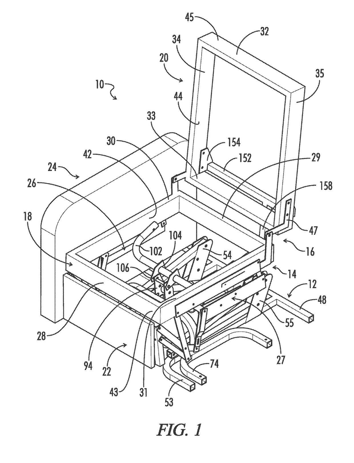
[0024]Referring now to the drawings, in which like numerals are used to designate like or corresponding parts throughout the various figures, FIG. 1 is a perspective view of an embodiment of a lift and recliner chair 10 in accordance with the invention in an upright position, with the left arm frame, from the point of view of a chair occupant, and all of the upholstery removed to illustrate the internal chair components and lift / recline mechanism underneath. Chair 10 generally includes a base frame 12, a lift and recline assembly 14 whic...


PUM


Abstract

A lift and recliner chair which is positionable in multiple reclining positions including both a Trendelenburg and zero-gravity position, in which using an electronic actuator mechanism the position of the back frame can be adjusted to any lift and/or reclining position the chair is capable of achieving without requiring any movement or adjustment to the position of the seat frame or footrest. The back frame actuator mechanism is secured between the back frame and a stationary position on the lift/recline frame, and has an increased stroke length and is synchronized with a separate lift/recline actuator to maintain the back frame in the same relative position with respect to the seat frame as the chair is moved to and from a reclining position.

Description

FIELD OF THE INVENTION[0001]The present invention relates to lift and reclining chairs, and more particularly to lift and reclining chairs having a back frame which is adjustable using an electronic control independent of the seat frame and footrest.BACKGROUND OF THE INVENTION[0002]Lift and recline chairs typically comprise a floor support or base section, a chair structure that includes at least a seat section, a back section, and a footrest section, which components are usually pivotally connected together by any number of different linkage arrangements, and a lift-recline mechanism connecting between the floor support and chair structure for moving the chair between a raised lift position and a reclining position. The use of one or more separate electronic actuators to control the movements of the lift-recline mechanism and adjust the position of the chair structure is known. Until recently, however, there was no ability to adjust the angle or incline of the chair back or back se...

Claims


Application Information

Patent Timeline
Patent Type & Authority Patents(United States)
IPC IPC(8): A47C1/024
CPCA47C1/024A47C1/0355
Inventor POLLARD, W. EDWARDOLCHESKI, JAMES
Owner GOLDEN TECH
Why Eureka
Try Eureka