
Identification method and identification system for an object's passing route direction

a technology of identification method and identification system, applied in direction finders using radio waves, instruments, individual entry/exit registers, etc., can solve problems such as ineffective application, system limitations on installation environment, and certain defects in the foregoing systems for identifying passing in and out situations of personnel and objects, so as to improve adaptability to a complicated environment, effective monitoring, and strong consistency

Inactive Publication Date: 2017-08-22
BEIJING LAUNCH TECH DEV
View PDF3 Cites 0 Cited by
  • Summary
  • Abstract
  • Description
  • Claims
  • Application Information

AI Technical Summary

Benefits of technology

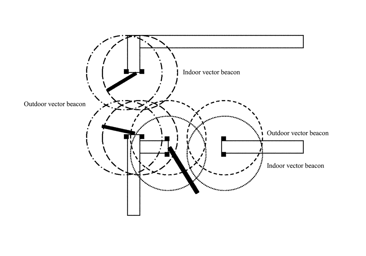
The present invention provides an identification method for an object's passing route direction using a system of vector beacons placed at preset intervals. The vector beacons send two low-frequency signals carrying different attribute codes according to a preset sequence, which form two low-frequency electromagnetic fields that are partially overlapped in space. The area of the overlapped part of the two low-frequency electromagnetic fields is no less than 70% of the total area or the maximum extension width of the independence part is less than 1 m. The method can effectively monitor the passing in and out situations of personnel or objects in a non-large space, improve adaptability to a complicated environment, and solve the problem in prior art that the double coil solution can only work in a sufficiently large and independent electromagnetic field region and cannot realize route identification in a smaller space. The low-frequency electromagnetic fields produced by the vector beacons have strong consistency, can effectively cover the monitoring area, avoid a blind identification zone, and have high identification efficiency.

Problems solved by technology

However, all the foregoing systems for identifying passing in and out situations of personnel and objects have certain defects.
For example, these systems have big limitations on the installation environments, cannot be effectively applied to such a smaller space environment as a most common door with a standard size, and have the defects of small application range, poor environmental adaptability, presence of blind identification zone, easily make incorrect identification and low practicability, or the like.

Method used


Image

  • Identification method and identification system for an object's passing route direction
  • Identification method and identification system for an object's passing route direction
  • Identification method and identification system for an object's passing route direction

Examples


Embodiment Construction

[0044]The vector beacon referred to in this application is used to transmit low-frequency encoded signals and to form low-frequency electromagnetic field around a beacon, which can be received by an identification unit. Beacon is usually used in pairs, with one pair in each group. If needed, multiple groups of beacons can be used.

[0045]The low-frequency signal referred to in this application may have a frequency within the range of 85K-150 KHz.

[0046]In the prior art, since the areas of independent parts of two low-frequency electromagnetic fields of coils need to be as big as possible so as to ensure the effective identification of a separation code, a system for identifying the passing in and out situations of personnel via double coils has many limitations on the installation environment, and cannot be effectively implemented in a narrow or complicated space environment.

[0047]Moreover, if the electromagnetic fields produced by the coils are expected to cover a common door with a w...


PUM


Abstract

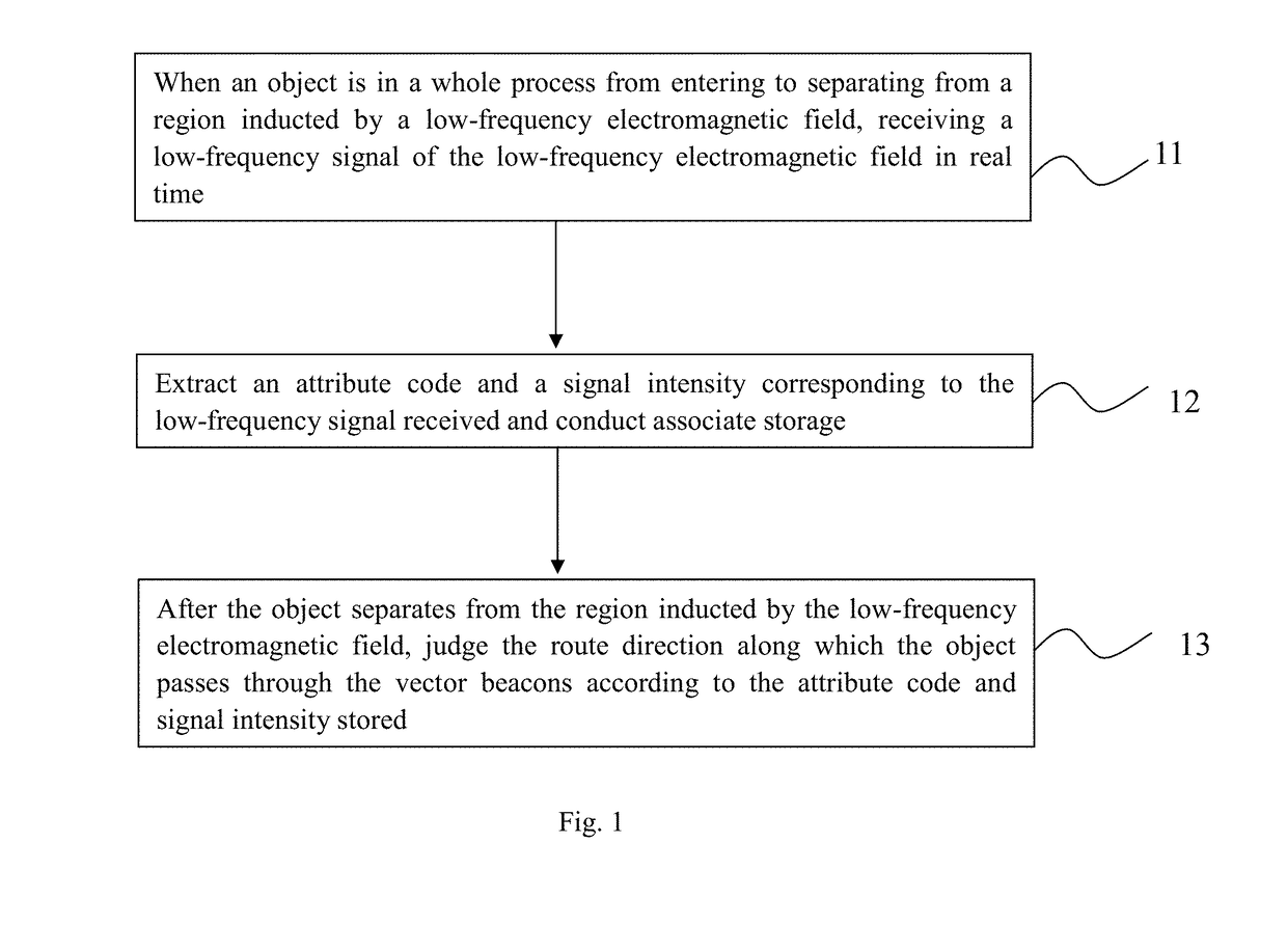
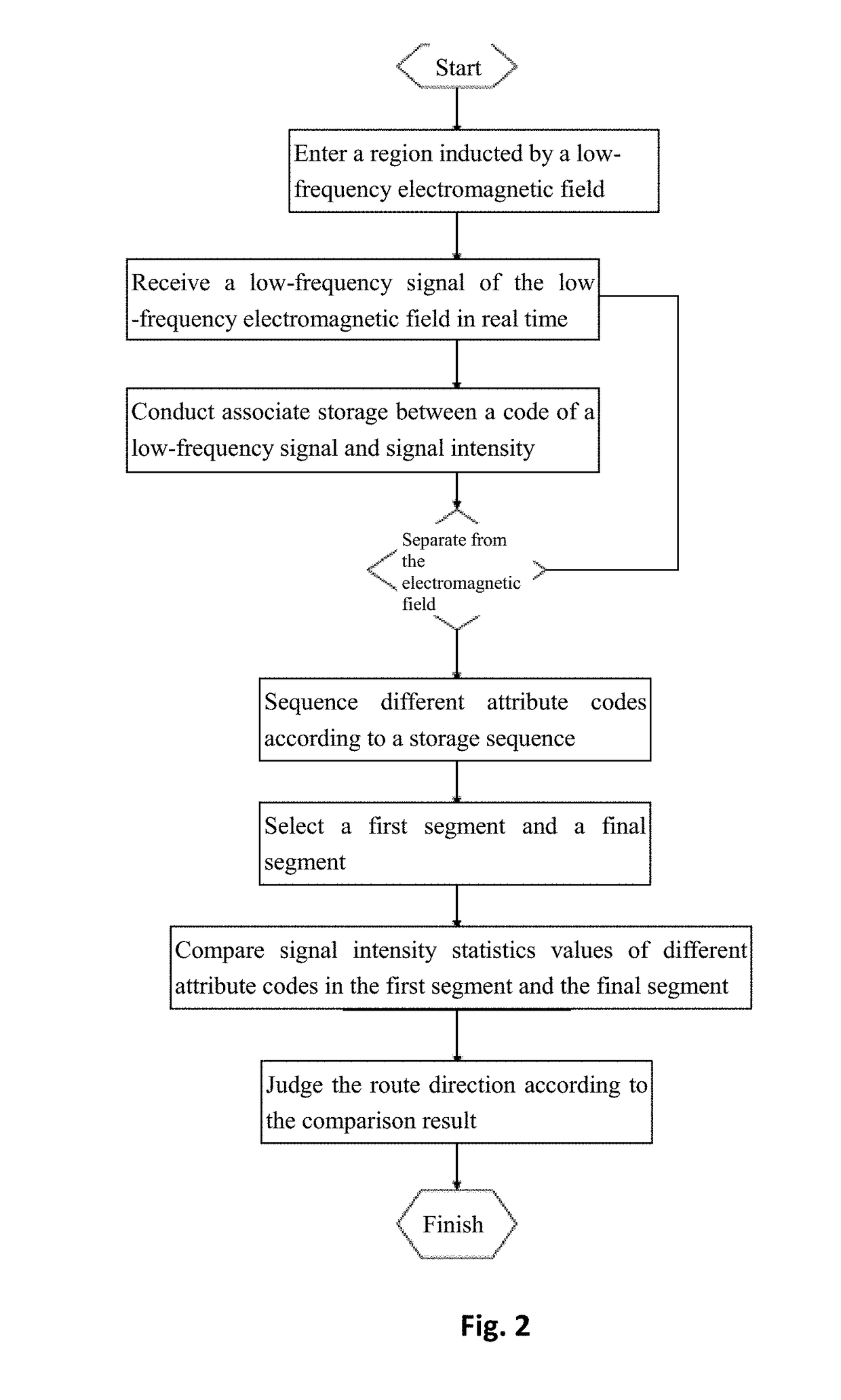
An identification method comprising: when an object is in a whole process from entering to separating from a region inducted by the low-frequency electromagnetic field, receiving the low-frequency signal of the low-frequency electromagnetic field in real time; extracting the attribute code and signal intensity corresponding to the low-frequency signal received and conducting associate storage; and after the object separates from the region inducted by the low-frequency electromagnetic field, determining the route direction along which the object passes through the vector beacons according to the attribute code and signal intensity stored.

Description

BACKGROUND OF THE INVENTION[0001]1. Field of the Invention[0002]The present invention relates to the field of route identification, and more particularly, to an identification method and an identification system for an object's passing route direction.[0003]2. Description of the Related Art[0004]Present systems for identifying passing in and out situations of personnel and objects mainly include: a system designed by a tag array, a system designed by a pair of directional antennas, a system designed by double coils, and the like. These systems are mainly applied to a channel type large space environment.[0005]However, all the foregoing systems for identifying passing in and out situations of personnel and objects have certain defects. For example, these systems have big limitations on the installation environments, cannot be effectively applied to such a smaller space environment as a most common door with a standard size, and have the defects of small application range, poor enviro...

Claims


Application Information

Patent Timeline
Patent Type & Authority Patents(United States)
IPC IPC(8): G01S3/12G01S3/14G01S1/08G07C9/00
CPCG01S3/12G01S1/08G01S3/143G07C9/00
Inventor CHEN, HAOWU, JIANZENG, JIANQIANG
Owner BEIJING LAUNCH TECH DEV
Learn More