Operating method of full-bridge modular multilevel converter boosting AC voltages for high voltage direct current transmission
a multi-level converter and ac voltage technology, applied in the field of multi-level power electronic converters, can solve the problems of reducing the transmission capacity of the converter, so as to reduce the cost of the converter and reduce the energy interaction
- Summary
- Abstract
- Description
- Claims
- Application Information
AI Technical Summary
Benefits of technology
Problems solved by technology
Method used
Image
Examples
embodiment 1
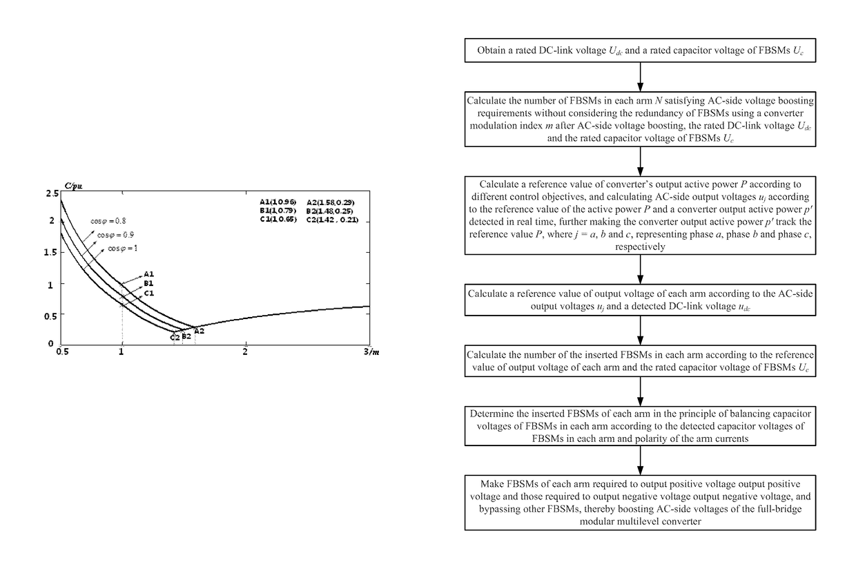
[0041]This embodiment is to illustrate advantages in improving transmission capacity of the converter and reducing converter cost while keeping RMS value of AC currents constant after AC-side voltage boosting. Quantitative analysis is give below for better understanding.
[0042]Firstly, the advantage of improving transmission capacity of a converter by boosting AC-side voltages is analyzed.
[0043]Transmission capacity of the converter S after AC-side voltage boosting can be expressed as
[0044]S=32UjmIjm,
where Ujm and Ijm are peak values of AC-side voltages and AC-side currents after AC-side voltage boosting respectively. Obviously, the transmission capacity of the converter will increase along with the increase of Ujm under a constant Ijm.
[0045]Next, advantage of reducing converter cost by boosting AC-side voltages is analyzed. Assuming the converter operates as a rectifier, take phase a for example, the instantaneous power flowing in the upper and lower arm can be expressed as:
[0046]...
embodiment 2
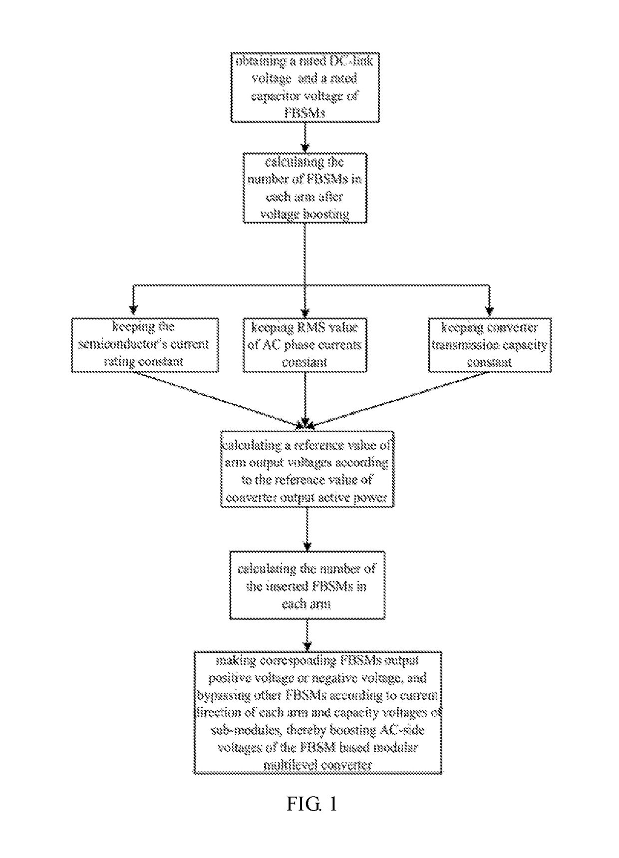
[0059]This embodiment is to illustrate advantages in reducing converter cost while keeping the semiconductor's current rating constant after AC-side voltage boosting. For better understanding, quantitative analysis is given in the following.
[0060]Assuming harmonic circulating currents are suppressed effectively, the RMS value of the arm current Ir can be expressed as:
Ir=√{square root over ((Idc / 3)2+(Im / 2√{square root over (5)})2)}
where Idc is the rated DC current and Im is peak value of AC-side currents.
[0061]Ignoring power loss of the converter, the relationship between Idc and Im can be expressed as:
[0062]Idc=34mImcosφ,
where m is converter modulation index and ω is power factor angle.
[0063]Furthermore, the relationship between Im and Ir can be derived as:
[0064]Im=4Irm2cos2φ+2.
[0065]Similar to the analysis in embodiment 1, the relationship between the required capacitance value of FBSMs C and converter modulation index m under the constant semiconductor's current rating...
embodiment 3
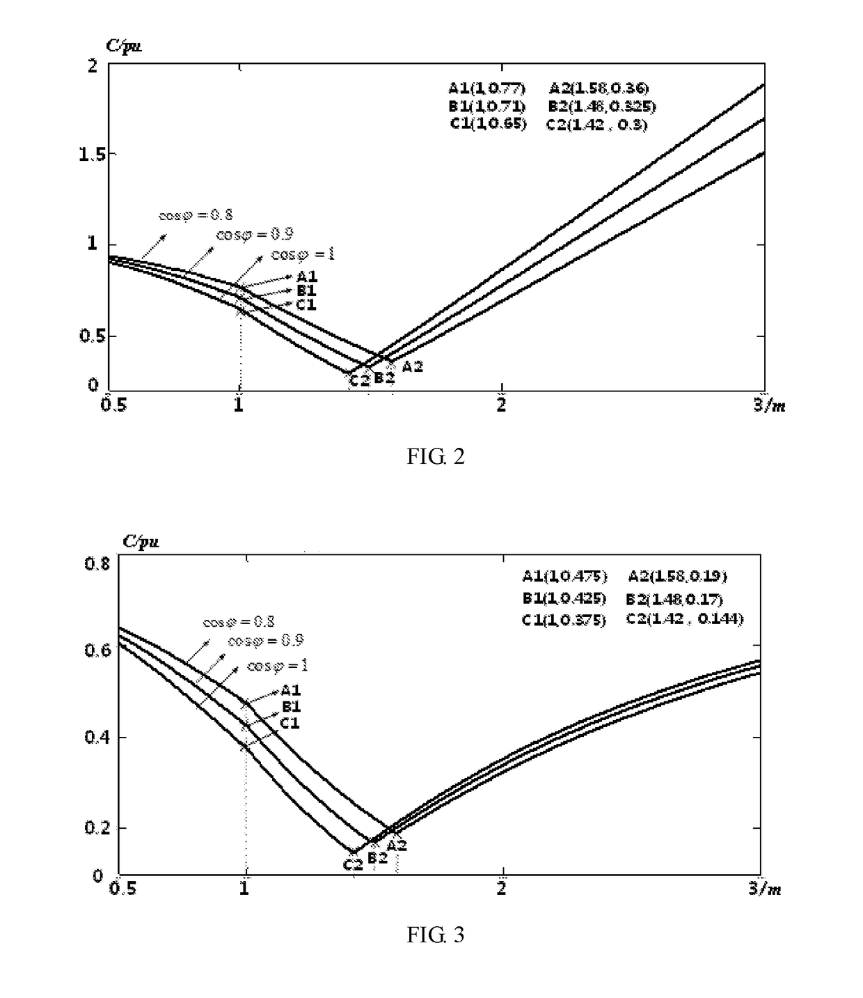
[0069]This embodiment is to illustrate advantages in reducing converter cost further and improving operating efficiency of the converter while keeping transmission capacity of the converter constant after AC-side voltage boosting. For better understanding, quantitative analysis is given in the following.
[0070]Firstly, advantage of reducing converter cost is analyzed.
[0071]Similar to the analysis in embodiment 1 and embodiment 2, the relationship between the required capacitance value of FBSMs C and converter modulation index m under the constant transmission capacity can be derived as:
[0072]C={Idc3ɛUcω1mcosφ[1-(mcosφ2)2]1.5,m≤12Idc3ɛUcω1m(1+m)cosφmax{[1-(mcosφ2)2]1.5,m2cosφ2(1-1m2)1.5},m>1,mcosφ / 21Idc3ɛUcω1(1+m)m(1-1m2)1.5,mcosφ / 2≥1.
[0073]FIG. 4 illustrates the relationships between the required capacitance value of FBSMs C and converter modulation index m with different power factors under the constant capacitor voltage ripple. Cle...
PUM
 Abstract
Description
Claims
Application Information
 - R&D
- Intellectual Property
- Life Sciences
- Materials
- Tech Scout
- Unparalleled Data Quality
- Higher Quality Content
- 60% Fewer Hallucinations
Browse by: Latest US Patents, China's latest patents, Technical Efficacy Thesaurus, Application Domain, Technology Topic, Popular Technical Reports.
© 2025 PatSnap. All rights reserved.Legal|Privacy policy|Modern Slavery Act Transparency Statement|Sitemap|About US| Contact US: help@patsnap.com


