Vehicle apparatus
a technology for vehicles and cameras, applied in the field of vehicle equipment, can solve the problems of vehicle movement, driver may stray out of the imaging range of the vehicle-mounted camera unintentionally, etc., and achieve the effect of improving safety
- Summary
- Abstract
- Description
- Claims
- Application Information
AI Technical Summary
Benefits of technology
Problems solved by technology
Method used
Image
Examples
first embodiment
1-1. Outline
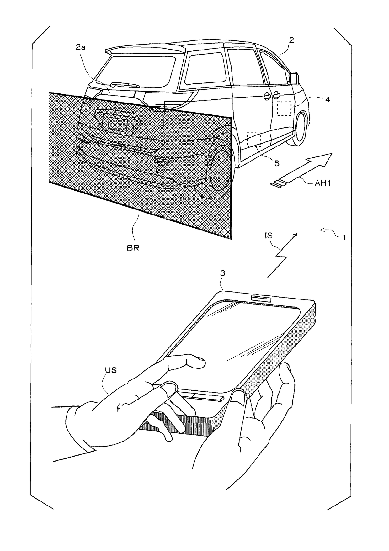
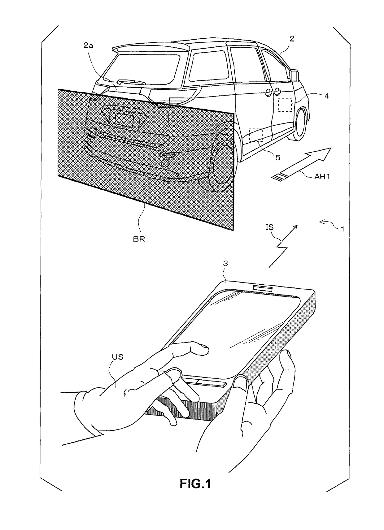
[0030]FIG. 1 illustrates a mode in which a user (mainly a driver) US adjusts the parking position of a vehicle 2 from outside the vehicle using a vehicle control system 1. The user US may park the vehicle 2 too close to an obstacle BR such as a fence at a parking lot partitioning off a parking region, and thereby, the user US may not be able to open a vehicle door such as a rear gate 2a. A vehicle front end portion may jut out over the parking region, and thereby, the vehicle 2 may become an obstacle to parking other vehicles. In this case, it is necessary for the user to re-board the vehicle, and to adjust the parking position. However, the user US requires skill when driving the vehicle for delicate adjustment of the parking position, and an unskillful user may have to re-adjust the parking position while going back and forth between a driver's seat and outside the vehicle several times.
[0031]In the vehicle control system 1, the user US confirms the distance between th...
second embodiment
2. Second Embodiment
2-1. Outline
[0131]Hereinafter, a second embodiment of the present invention will be described with reference to the accompanying drawings.
[0132]FIG. 9 illustrates a mode in which the user (mainly a driver) US controls the vehicle control system 1 from outside the vehicle such that the vehicle 2 moves rearward, and is parked.
[0133]The user US by himself may not be able to park the vehicle 2 in a desired parking region. For example, the user US may park the vehicle 2 too close to the obstacle BR such as a fence partitioning off the parking region, and thereby, the user US may not be able to open a vehicle door such as the rear gate 2a, or the vehicle front end portion may jut out over the parking region, and thereby, the vehicle 2 may become an obstacle to parking other vehicles. In this case, it is necessary for the user to re-board the vehicle, and to adjust the parking position. However, the user US requires skill when driving the vehicle for delicate adjustment...
modification example
2-4. Modification Example
[0225]The second embodiment has been described up to this point; however, the present invention is not limited to the second embodiment, and can be modified. Hereinafter, a modification example will be described. The aforementioned embodiment and embodiments to be described hereinbelow can be appropriately combined.
[0226]In the second embodiment, the vehicle-mounted camera 220 is used as a device for detecting a motion of the user. However, a 3-dimensional laser radar may be used in replacement of the vehicle-mounted camera 220. Any type of device may be used insofar as the device can detect a motion of the user.
[0227]In the second embodiment, a movement instruction indicated by a motion of the user is recognized by the first recognition unit 410a and the second recognition unit 410b. However, the first recognition unit 410a and the second recognition unit 410b may be configured as a single recognition unit. In this case, the single recognition unit recogniz...
PUM
 Abstract
Description
Claims
Application Information
 - R&D
- Intellectual Property
- Life Sciences
- Materials
- Tech Scout
- Unparalleled Data Quality
- Higher Quality Content
- 60% Fewer Hallucinations
Browse by: Latest US Patents, China's latest patents, Technical Efficacy Thesaurus, Application Domain, Technology Topic, Popular Technical Reports.
© 2025 PatSnap. All rights reserved.Legal|Privacy policy|Modern Slavery Act Transparency Statement|Sitemap|About US| Contact US: help@patsnap.com


