
Radio tag

a radio tag and actuator technology, applied in the field of radio tags, can solve the problems of complex method of manufacturing radio tags, large vertical size of actuators, and large size of actuators, and achieve the effect of simple manufacturing

Inactive Publication Date: 2017-08-01
COMMISSARIAT A LENERGIE ATOMIQUE ET AUX ENERGIES ALTERNATIVES
View PDF8 Cites 0 Cited by
  • Summary
  • Abstract
  • Description
  • Claims
  • Application Information

AI Technical Summary

Benefits of technology

The claimed radio tag has the advantage of being easy to manufacture, with the antenna and actuator being deposited onto the same substrate using the same methods. This simplifies the process of manufacturing the radio tag and reduces the complexity of the electrical connections between them. The use of a shape-memory material as the actuator allows for detection of temperature or magnetic field thresholds, and the use of a transducer material that is irreversible in its deformation allows for storage of the crossing of a specific threshold even without a reader. Overall, the radio tag remains simple and easy to use while being highly effective in detecting specific thresholds.

Problems solved by technology

Furthermore the vertical size of the actuator is relatively large due to the vertical movement of the plate.
However, this radio tag is also complex to implement since the manufacture of an electrical switch from shape-memory material is no simple matter, as the author of this article himself underlines.
Thus, as previously, this method of manufacturing the radio tag is complex to implement.
However, the same production problems are encountered with a radio tag capable of detecting a variation in the magnetic field in which it is immersed.

Method used


Image

  • Radio tag
  • Radio tag

Examples


Embodiment Construction

[0045]In these figures, the same references are used to denote the same elements. In this description below, the characteristics and functions well known to the person skilled in the art are not described in detail.

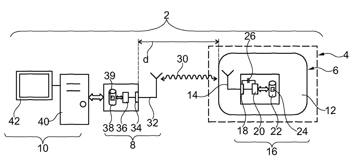
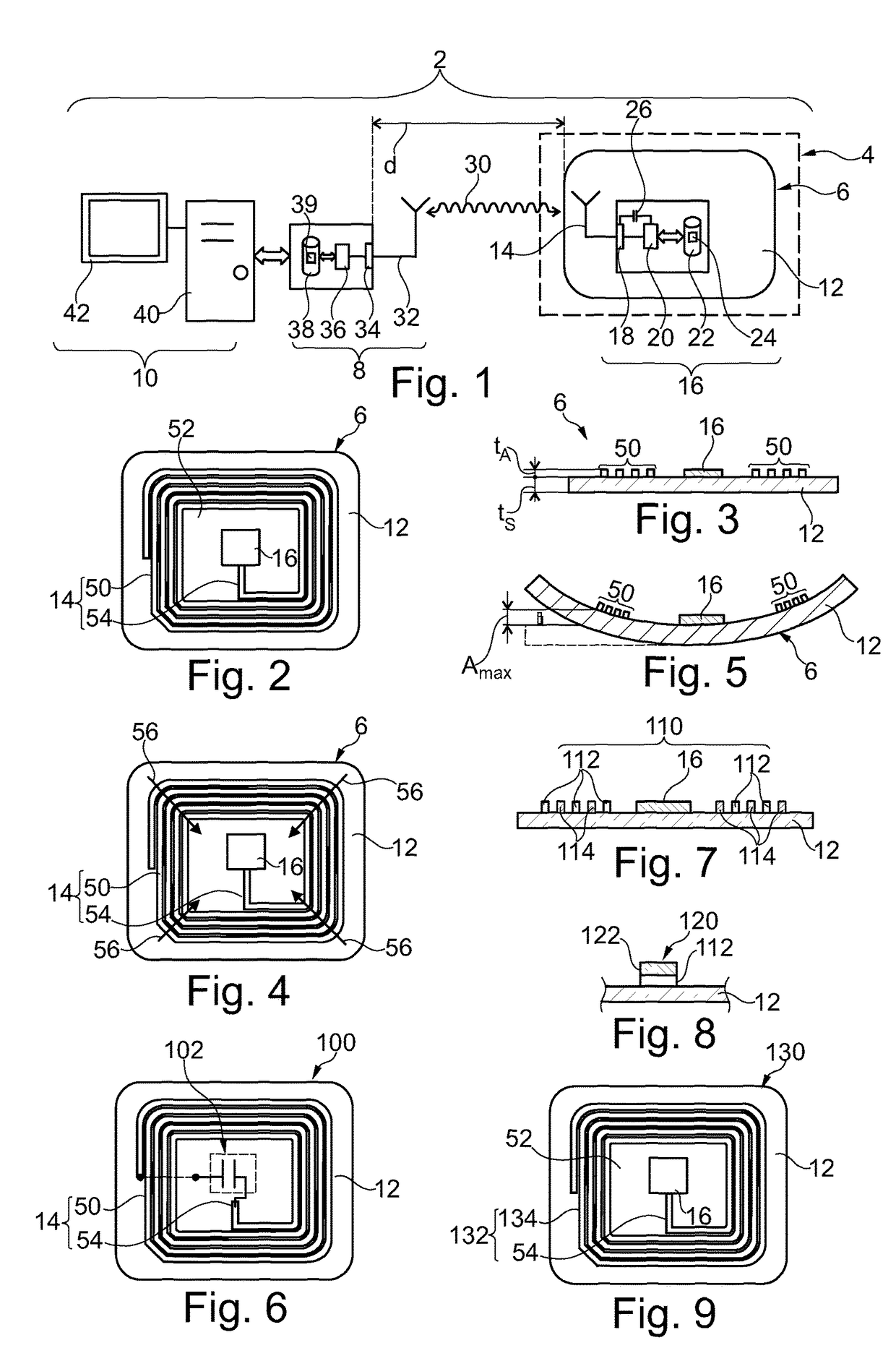
[0046]FIG. 1 shows an assembly 2 for detecting the crossing of a predetermined threshold ST by an energy variation chosen from the group consisting of a temperature variation and a magnetic field variation. In the particular case described here, the assembly 2 is used to detect a variation in temperature of an object 4. The object 4 is, for example, a packaging, a package, a living being or any other object to which a radio tag can be attached or affixed.

[0047]For this purpose, the assembly 2 comprises:[0048]a radio tag 6 rigid with the object 4,[0049]a reader 8 of the radio tag 6, and[0050]a device 10 for processing the information read by the reader 8.

[0051]The radio tag 6 is affixed, for example, without any degree of freedom, to the object 4 if this object can become ...


PUM

PropertyMeasurementUnit
temperatureaaaaaaaaaa
degree of freedomaaaaaaaaaa

Abstract

A radio tag capable of indicating to a reader, via a wireless link, that a variation in energy has crossed a predetermined threshold, this variation in energy being chosen from the group made up of a variation in the temperature of the radio tag and a variation in the magnetic field in which the radio tag is immersed. This radio tag includes transducer material chosen from a group made up of a thermal shape-memory material, a magnetostrictive material and a magnetic shape-memory material. This transducer material is deposited and affixed without any degree of freedom onto a substrate or an antenna of the radio tag to form, with the substrate or the antenna, a multilayer structure which flexurally deforms the antenna between a bent conformation and a less bent conformation when the energy variation crosses the predetermined threshold.

Description

BACKGROUND[0001](1) Field[0002]The invention relates to a radio tag capable of indicating to a reader, via a wireless link, that a variation in energy has crossed a predetermined threshold, this variation in energy being chosen from the group consisting of a variation in the temperature of the radio tag and a variation in the magnetic field in which the radio tag is immersed. The invention also relates to an assembly comprising this radio tag and a reader.[0003](2) Description of the Related Art[0004]Radio tags are also known as RFID (Radio Frequency Identification) tags.[0005]Known radio tags comprise:[0006]an electrically insulating substrate,[0007]an antenna to set up the wireless link with the reader, this antenna being entirely deposited and affixed without any degree of freedom onto the insulating substrate, and[0008]an actuator capable of modifying the impedance of this antenna when the energy variation crosses the predetermined threshold in order to indicate this event to th...

Claims


Application Information

Patent Timeline
Patent Type & Authority Patents(United States)
IPC IPC(8): G06K7/10G06K19/07G01K5/48
CPCG06K7/10316G01K5/483G06K19/0717G06K19/0724
Inventor ALARCON RAMOS, JUVENALVIALA, BERNARD
Owner COMMISSARIAT A LENERGIE ATOMIQUE ET AUX ENERGIES ALTERNATIVES
Learn More