
Filter medium layer and filter device provided with same

a filter medium and filter device technology, applied in gravity filters, separation processes, loose filtering materials, etc., can solve the problems of clogging, increasing filtration pressure, and difficulty in selecting filter media for liquid to be treated, so as to achieve effective filtration and increase the filtration duration time

Active Publication Date: 2017-08-01
ISHIGAKI CO LTD
View PDF24 Cites 7 Cited by
  • Summary
  • Abstract
  • Description
  • Claims
  • Application Information

AI Technical Summary

Benefits of technology

The patent text describes a filter that uses two types of media with different grain sizes to capture suspended solids efficiently throughout the filter. By mixing these media in a specific way, the breakthrough phenomenon is prevented and the amount of solids captured is maintained. This results in a stable, efficient filter that can perform depth filtration and requires less frequent cleaning.

Problems solved by technology

In the case of performing a filtration operation using granular or fiber filter media, it is difficult to select filter media for a liquid to be treated.
However, the filtration results in surface filtration in which a large amount of suspended solids are captured by the filter media near the surface of the filter medium layer.
This causes clogging quickly and the filtration pressure is increased.
However, since a deepest portion of the filter medium layer is not effectively utilized for filtration, the number of the cleaning processes is increased for the amount of suspended solids captured, and thus a treatment amount is reduced.
While the filtration pressure is not significantly increased, the quality of the treated liquid is poor and the suspended solids contained in the liquid to be treated flow out together with the treated liquid even in an early stage after the start of filtration (a breakthrough phenomenon).
However, the treatment speed is low because only the gaps between the filter media are used as the flow passages inside the filter tank.
There is a possibility that lumps of suspended solids in the gaps, which have failed to be released during the filter medium cleaning, are left in the filled layer.

Method used


Image

  • Filter medium layer and filter device provided with same
  • Filter medium layer and filter device provided with same
  • Filter medium layer and filter device provided with same

Examples


first embodiment

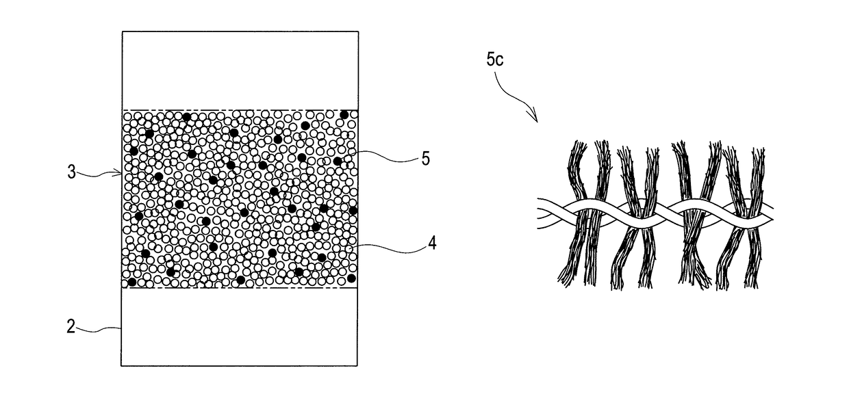
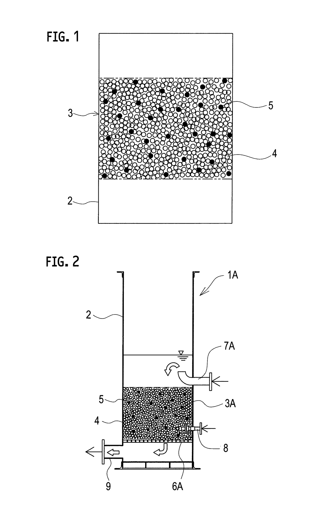
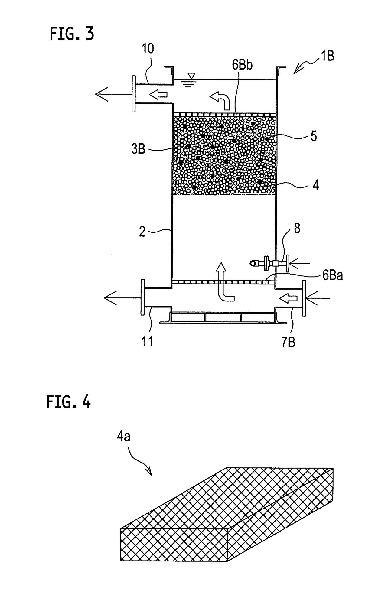
[0105]Each of filter devices 1A and 1B according to a first embodiment separates and removes suspended solids contained in a liquid to be treated such as living drainage (wastewater) and industrial drainage (wastewater), for example, with a filter medium layer 3 using a plurality of filter media bodies 4 and a plurality of filtering aids bodies 5. Note that the filter medium layer means a filter medium layer made of a filtering material (assembly of the filter media and the filtering aids). The plurality of filter media bodies 4 are in contact with one another and are separable from one another. The filter medium layer 3 is configured to capture suspended solids contained in a liquid to be treated in gaps between the filtering bodies. The plurality of filtering aids bodies 5 are in contact with adjacent ones of the filter media bodies and are separable from each other and from the filter media bodies. The filtering aids bodies 5 are configured to allow the suspended solids contained...

second embodiment

[0177]A filter device 101 according to a second embodiment performs separation cleaning of suspended solids contained in a liquid to be treated such as living drainage (wastewater) and industrial drainage (wastewater), for example, with a filter medium layer 103 using floating filter media 104 and filtering aids 105.

[0178]FIG. 15 is a schematic configuration diagram of the filter medium layer 103. A filter tank 102 is filled with the filter media 104 and the filtering aids 105 to form the filter medium layer 103 in a state where the filter media and the filtering aids are mixed. In floating filtration, assuming that the specific gravity of the liquid to be treated as a filtration target is 1.0, the apparent specific gravity of the filter medium 104 and the filtering aid 105 is each less than 1.0. Since the specific gravity of the filter medium 104 and the filtering aid 105 is each less than 1.0, the filter medium layer 103 is formed in an upper part of the filter tank 102, resulting...

third embodiment

[0234]A filter device 201 according to a third embodiment performs treatment of sewage generated in a sewage treatment plant or industrial wastewater or purification of lakes, rivers and the like, for example, with a filter medium layer 203 using sinking filter media 204 and filtering aids 205. The filter device 201 captures not only suspended solids in a liquid to be treated (raw water) on a surface layer of the filter medium layer 203 but also impurities inside the filter medium layer 203. In the filter device 201, the filter medium layer 203 is formed of the filter media 204 having a function to capture the suspended solids and the filtering aids 205 having a function to pass the liquid. The filter media having different functions are dispersed in the filter medium layer 203, and some of the suspended solids are carried deep down in the filter medium layer 203. Accordingly, the suspended solids are captured in the entire filter medium layer 203. By adjusting a volume mixing ratio...


PUM

PropertyMeasurementUnit
specific gravityaaaaaaaaaa

Abstract

A filter medium layer includes filter media configured to capture suspended solids contained in a liquid to be treated and filtering aids configured to allow the suspended solids contained in the liquid to be treated to pass through the filtering aids. The filter media and the filtering aids are mixed together and the liquid to be treated is filtered by being passed through the filter media and the filtering aids as mixed together. A filter device includes the filter medium layer and a filter tank configured to accommodate the filter medium layer.

Description

TECHNICAL FIELD[0001]The present invention relates to a filter medium layer for separating and removing suspended solids contained in a liquid to be treated (raw water), and a filter device provided with the same.BACKGROUND ART[0002]Many filter devices each having a filter medium layer formed of granular filter media are used for solid-liquid separation and biotreatment equipment. The above filter devices perform surface filtration in which suspended solids in a liquid to be treated are mainly captured on a surface of the filter medium layer. In the surface filtration, the captured suspended solids are accumulated on the surface of the filter medium layer, and cause clogging of the filter medium layer even when the entire filter medium layer is not effectively utilized. For this reason, a filtration pressure rises in a short time and the filter media needs cleaning frequently. When flow passages (gaps between adjacent gains of the filter media) in the filter medium layer are narrow,...

Claims


Application Information

Patent Timeline
Patent Type & Authority Patents(United States)
IPC IPC(8): B01D24/02B01D39/08B01D39/16B01D24/10B01D24/12B01D24/16B01D39/02B01D39/06B01D39/04
CPCB01D24/10B01D24/02B01D24/12B01D24/165B01D39/083B01D39/1676B01D39/02B01D39/04B01D39/06
Inventor FUJITA, KUNIOUJIKE, HIDETAKA
Owner ISHIGAKI CO LTD
Learn More