Multi-input reduction gear having input/output position feedback

a technology of input/output displacement and feedback, which is applied in the direction of gearing, program-controlled manipulators, joints, etc., can solve the problems of inability to sense the absolute output position and input/output displacement information applied to the control of automatic devices, cumbersome preparation of additional units, and difficulty in changing input methods. to achieve the effect of accurate control

Active Publication Date: 2017-07-25
ROBOTIS
View PDF11 Cites 0 Cited by
  • Summary
  • Abstract
  • Description
  • Claims
  • Application Information

AI Technical Summary

Benefits of technology

[0029]According to the embodiment of the present invention, because an input / output feedback unit and an input mediating unit included in a reduction gear is detachable, an input method for making an automatic device is easy, and because a stacked coupling structure is realized, a plurality of mechanical components can be selectively adopted.
[0030]In addition, since positions of an input unit and an output unit are fed back by the input / output feedback unit included in the reduction gear having a detachable coupling structure, there is an effect where more elaborate and accurate control becomes possible.
[0031]Effects of the present invention are not limited to above-described effects, it should be understood that all effects which may be inferred from the present invention described in the modes of the invention or claims are included thereto.

Problems solved by technology

Accordingly, it is difficult to change the input method after the reduction gear (20) is manufactured, and since power transmitted by the reduction gear (20) cannot be controlled, and thus, information of an absolute output position and input / output displacement cannot be sensed and applied to a control of the automatic device.
In addition, since an integrated conventional reduction gear (20) is not adaptable to a driving unit having various driving types, there is a limitation to selecting an input driving unit, and thus, it is cumbersome to prepare an additional unit which connects the reduction gear (20) and the input driving unit.
Accordingly, since a structure of the reduction gear (20) becomes complex, maintenance cost such as processing cost and manufacturing cost is high, and since the entire volume of the reduction gear (20) becomes increased, there is a disadvantage in miniaturization of the reduction gear (20).

Method used


Image

  • Multi-input reduction gear having input/output position feedback
  • Multi-input reduction gear having input/output position feedback
  • Multi-input reduction gear having input/output position feedback

Examples


Embodiment Construction

[0044]Hereinafter, the present invention will be described in detail with reference to the accompanying drawings. However, embodiments of the present invention may be implemented in several different forms and are not limited to embodiments described herein. In addition, parts irrelevant to description are omitted in the drawings in order to clearly explain embodiments of the present invention. Similar parts are denoted by similar reference numerals throughout this specification.

[0045]Throughout this specification, when a part is referred to as being “connected” to another part, it includes “directly connected” and “indirectly connected” via an intervening part. Also, when a certain part “includes” a certain component, other components are not excluded unless explicitly described otherwise, and other components may in fact be included.

[0046]Hereinafter, embodiments of the present invention will be described in detail with reference to accompanying drawings.

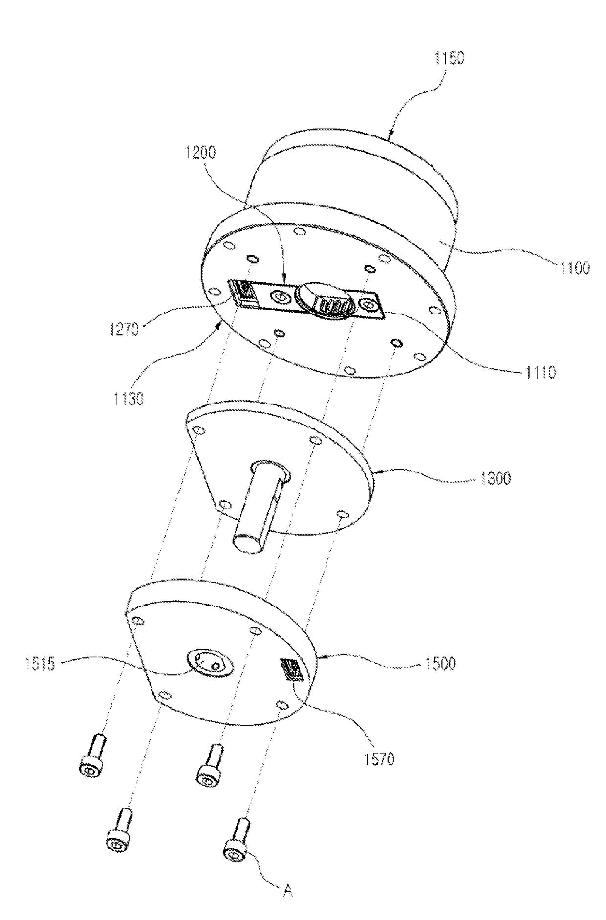
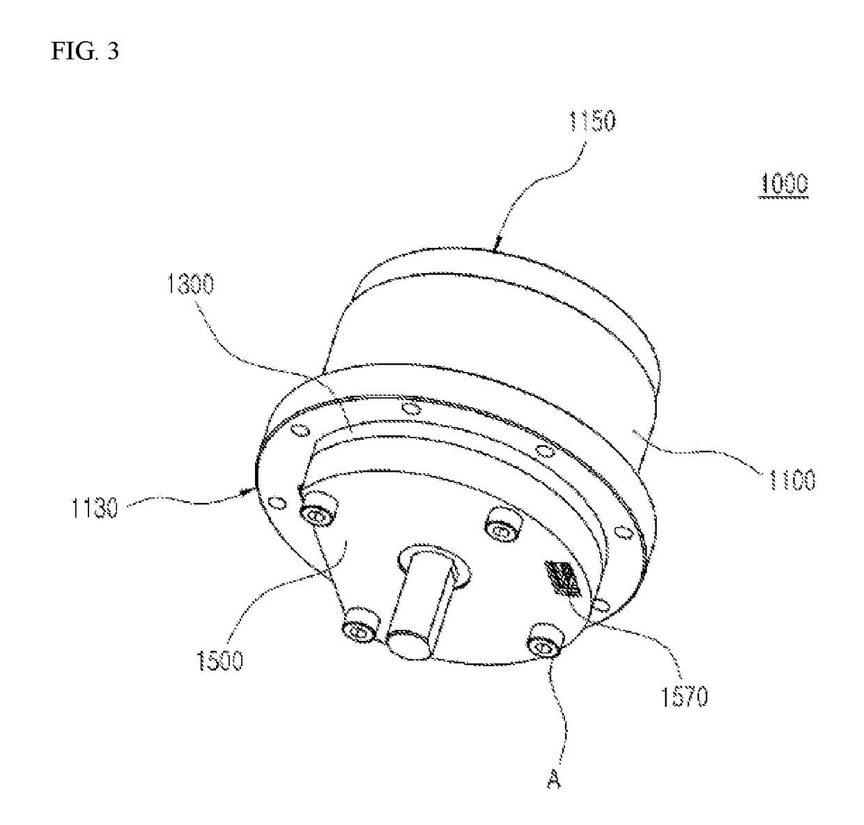
[0047]FIG. 3 is a view ill...


PUM


Abstract

Disclosed is a multi-input reduction gear having an input / output position feedback, including: a reduction gear body including an input unit and an output unit; an output feedback unit which is detachably provided in the reduction gear body and detects a position of the output unit; an input mediating unit which is detachably provided in the reduction gear body, is connected to a shaft of a power source, and transmits power to the input unit; and an input feedback unit which is stacked between and coupled to the reduction gear body and the input mediating unit and detects a position of the input unit.

Description

CROSS REFERENCE TO PRIOR APPLICATIONS[0001]This application is a National Stage Application of PCT International Patent Application No. PCT / KR2014 / 003740 filed on Apr. 28, 2014, under 35 U.S.C. §371, which claims priority to Korean Patent Application No. 10-2014-0050947 filed on Apr. 28, 2014, which are all hereby incorporated by reference in their entirety.TECHNICAL FIELD[0002]The present invention relates to a multi-input reduction gear having an input / output position feedback, and more particularly, to a multi-input reduction gear having an input / output position feedback so that an automatic device is easily made.BACKGROUND ART[0003]From industrial robots to humanoid robots, in various fields involving using robots, an actuator is generally used that has a speed reduction function for smooth joint movement.[0004]Particularly, in robotics technology which has been developing rapidly recently, robotics mechanisms which have been conventionally applied only to industrial fields are ...

Claims


Application Information

Patent Timeline
Patent Type & Authority Patents(United States)
IPC IPC(8): F16H1/32B25J9/10B25J17/00
CPCB25J17/00B25J9/102F16H1/32F16H1/321B25J9/08B25J19/00
Inventor KIM, BYOUNG SOOHA, IN YONGLEE, JUNG HO
Owner ROBOTIS
Why Eureka
Try Eureka