
UVA battery connector

a battery connector and battery technology, applied in the direction of coupling contact members, coupling device connections, electrical equipment, etc., can solve the problems of plastic deformation and in turn damage, and achieve the effects of strong structural strength, high plug times, and easy manufacturing

Active Publication Date: 2017-07-18
MOLEX INC
View PDF13 Cites 17 Cited by
  • Summary
  • Abstract
  • Description
  • Claims
  • Application Information

AI Technical Summary

Benefits of technology

The present patent text describes a terminal design that prevents damage to elastic terminals and improves soldering. The design includes a protruding rail and guide grooves that allow elastic terminals to enter terminal grooves without bending or damage. The elastic terminals also have an increased soldering area for a more secure soldering connection.

Problems solved by technology

However, the spherical bulge is generally formed by stamping a metal sheet to make a part of the metal sheet curved so as to protrude at a side and be recessed at an opposite side so that the inside of the spherical bulge is hollow, the spherical bulge is easily recessed from the protruding side toward the inside of the spherical bulge and plastically deformed and in turn be damaged after many times collisions.

Method used


Image

  • UVA battery connector
  • UVA battery connector
  • UVA battery connector

Examples


Embodiment Construction

[0034]Before the present disclosure is described in detail, it should be noted that similar element is indicated by the same reference numeral in the following description.

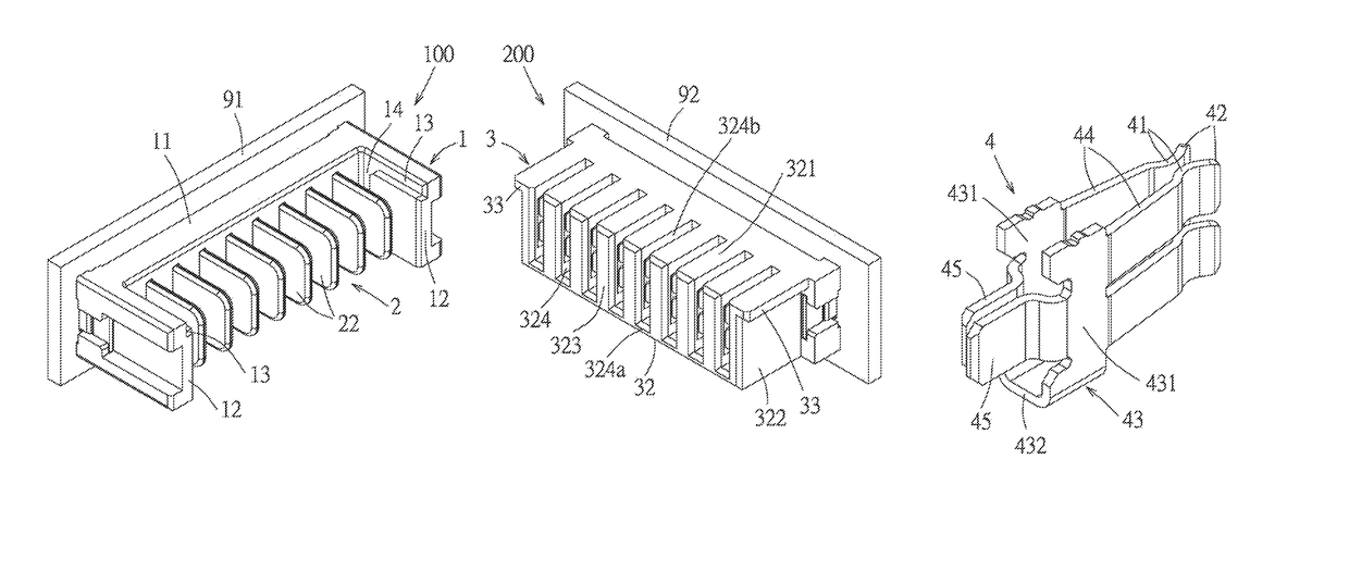
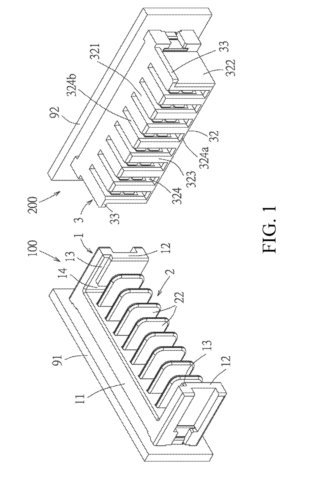
[0035]Referring to FIG. 1, an electrical connection device of a first embodiment of the present disclosure comprises a first connector 100 and a second connector 200. In the embodiment, the first connector 100 is provided to a first circuit board 91, the second connector 200 is provided to a second circuit board 92.

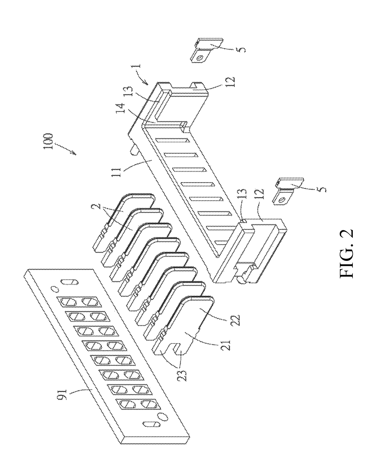
[0036]Referring to FIG. 1 to FIG. 3, the first connector 100 comprises an insulating body 1, a plurality of blade-type terminals 2 and two fixing members 5. The insulating body 1 has a base portion 11 which is longitudinally long and two ear portions 12 which perpendicularly protrude respectively from two ends of the base portion 11, are spaced apart from each other and face each other. In the embodiment, an inner wall surface of each ear portion 12 is provided with a first guide groove 13 which is perp...


PUM


Abstract

An electrical connection device and a terminal are provided. The electrical connection device includes first and second connectors. The first connector includes an insulating body and a plurality of blade-type terminals. The insulating body has a base portion and two ear portions, an inner wall surface of the ear portion has a first guide groove which is perpendicular to the base portion and a second guide groove which is parallel to the base portion. The second connector includes an insulating housing and a plurality of elastic terminals. The insulating housing has a mating portion and a protruding rail, the mating portion has a plurality of terminal grooves respectively provided with the elastic terminals. When the connectors are mated, each contact portion can contact the guide portion of the corresponding elastic terminal and then contact the contact portion of the corresponding elastic terminal to prevent the elastic terminal from being damaged.

Description

RELATED APPLICATIONS[0001]This application claims priority to Chinese Application No. 201510498478.6, filed Aug. 13, 2015, which is incorporated herein by reference in its entirety.TECHNICAL FIELD[0002]The present disclosure relates to an electrical connection device, and particularly relates to an electrical connection device having two mating directions.BACKGROUND ART[0003]Generally a mating connector which may have two directions, for example, as disclosed in Chinese patent issued publication No. CN202454786U, comprises: a first insulating body provided with a plurality of terminal grooves, each terminal groove has a horizontal opening opened in a horizontal direction and a vertical opening opened in a vertical direction, each terminal groove is correspondingly provided with a clamping arm-type terminal; and a second insulating body provided with a plurality of blade-type terminals respectively mating with the plurality of clamping arm-type terminals. Two sides of the first insul...

Claims


Application Information

Patent Timeline
Patent Type & Authority Patents(United States)
IPC IPC(8): H01R13/631H01R13/04
CPCH01R13/631H01R13/04H01R13/055H01R13/112H01R13/113H01R12/73H01R12/737
Inventor HO, YI-TSE
Owner MOLEX INC
Learn More