
Method and device for the mechanical or mechanical-biological treatment of waste

a technology of mechanical or mechanical-biological treatment and waste, which is applied in the direction of grain treatment, waste based fuel, fuel, etc., can solve the problems of high technical cost, large area and time consumption during the final rotting of such waste, and high water consumption, so as to reduce water content and water content. the effect of long residence time and reducing water conten

Active Publication Date: 2017-07-18
ZWECKVERBAND ABFALLBEHANDLUNG KAHLENBERG
View PDF20 Cites 4 Cited by
  • Summary
  • Abstract
  • Description
  • Claims
  • Application Information

AI Technical Summary

Benefits of technology

This approach ensures a high biogenic component in the fuels, optimizing the treatment process, reducing water consumption, and maintaining a consistent quality of the substitute fuels, while minimizing environmental impact and operational complexity.

Problems solved by technology

The biomass to be decomposed is thus not reutilized further and the area and time consumption during the final rotting of such waste is comparatively large.
A disadvantage of this method is a comparatively large water consumption, wherein the water outlets are easily clogged by penetrating waste, this requiring high technical outlay for cleaning and keeping the outlets clear.
It has also been shown that, as a result of intensive aeration of the waste, aerobic hydrolysis is not substantially promoted and is not essential for the process.

Method used


Image

  • Method and device for the mechanical or mechanical-biological treatment of waste
  • Method and device for the mechanical or mechanical-biological treatment of waste
  • Method and device for the mechanical or mechanical-biological treatment of waste

Examples


Embodiment Construction

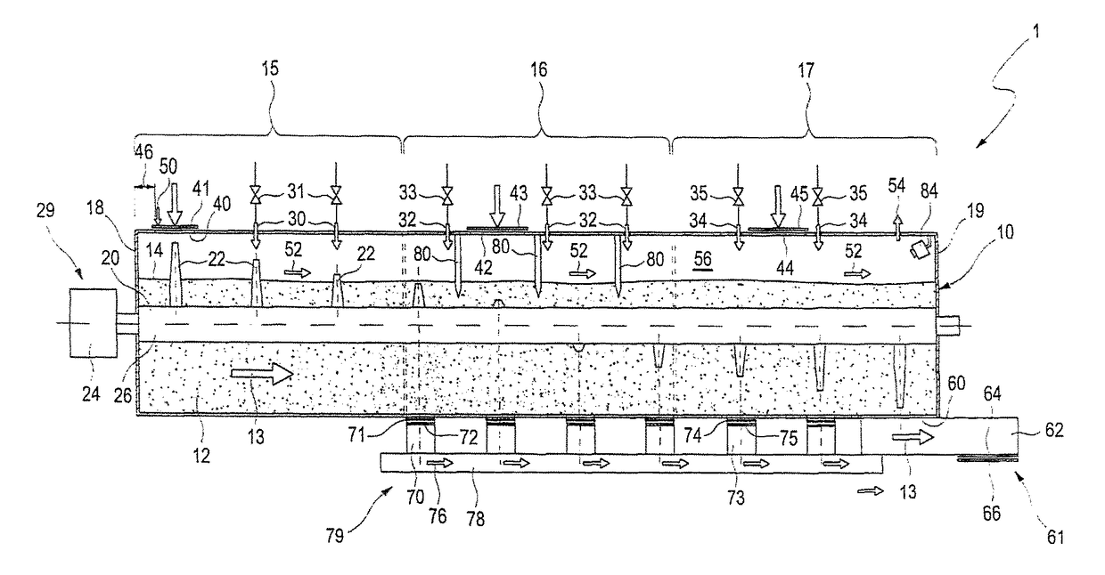
[0069]FIG. 1 shows a schematic illustration of the waste treatment plant according to the invention in an illustration from the side.

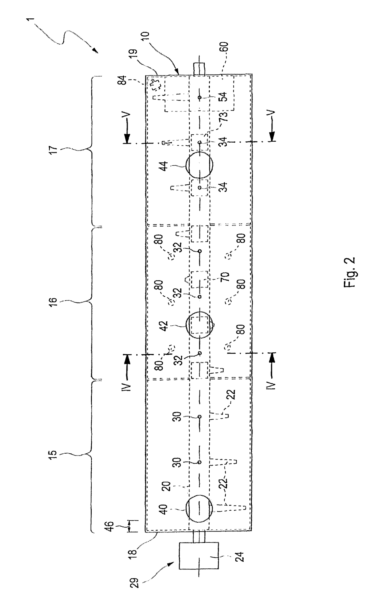
[0070]FIG. 1 shows a reactor container 10, which is embodied as a horizontal container. The length of the reactor container 10 is typically in the range from 20 m to 30 m. In the lower region, the cross section of the reactor container is preferably round, in particular embodied as a circular area. The diameter of the container 10 is between 3 m and 6 m. In the upper region, in addition to rounded geometries, angular, for example rectangular geometries, are also possible. Examples are given in the subsequent views from the front. The reactor container 10 accommodates an agitator shaft 20 which passes through the reactor container 10 along the entire length from the front end wall 18 to the rear wall 19. In the embodiment illustrated in FIG. 1, the agitator shaft 20 breaches the end wall 18 and the rear wall 19. On the side of the end wall 18, an agitat...


PUM

PropertyMeasurementUnit
lengthaaaaaaaaaa
diameteraaaaaaaaaa
diameteraaaaaaaaaa

Abstract

A method for treating waste in a mechanical or mechanical-biological waste treatment plant is provided. Waste is introduced into the waste treatment plant at at least one input point, the waste is homogenized by way of at least one agitator and the consistency of the waste in the waste treatment plant is determined. Water or waste which has a higher water content than the waste in the waste treatment plant is added in one scenario. Water is removed or waste having a lower water content is added in another scenario. Further, the method involves transporting the introduced waste to at least one output point, and removing the waste. The waste treatment plant is subdivided into at least two zones and in each zone the consistency of the waste is regulated separately by the input of waste and / or addition or removal of water.

Description

CROSS REFERENCE TO RELATED APPLICATIONS[0001]This is a US national stage application of PCT / EP2012 / 003161 filed Jul. 25, 2012, which claims priority to EP Application No. 11176112.8, filed Aug. 1, 2011 and EP Application No. 11007924.1, filed Sep. 29, 2011, the entireties of which are hereby incorporated by reference.[0002]The invention relates to a method for the treatment of waste in a mechanical or mechanical-biological waste treatment plant, and to a device for the mechanical or mechanical-biological treatment of waste.PRIOR ART[0003]Since 2005 in Germany, it has only been possible to deposit waste, in particular municipal waste and domestic waste, at a landfill when it has been pretreated. The assignment criteria with which the pretreated waste has to comply are defined in the German landfill ordinance (Deponieverordnung, DepV). Essentially, the biogenic component and the combustible constituents in the waste in question have to be reduced considerably in order that the assignm...

Claims


Application Information

Patent Timeline
Patent Type & Authority Patents(United States)
IPC IPC(8): B02C23/00C10L5/40B02C18/00B02C17/18C10L5/46C10L5/48B02C23/02
CPCC10L5/40B02C17/1815B02C18/0084B02C18/0092B02C23/02C10L5/46C10L5/48Y02E50/10Y02E50/30
Inventor GIBIS, GEORGPERSON, GEORG
Owner ZWECKVERBAND ABFALLBEHANDLUNG KAHLENBERG
Learn More