Hierarchical feedback-controlled oscillator techniques

Active Publication Date: 2017-07-04
ALLLE INC
View PDF4 Cites 1 Cited by
  • Summary
  • Abstract
  • Description
  • Claims
  • Application Information

AI Technical Summary

Benefits of technology

This patent text describes techniques related to feedback-controlled oscillators, which are used to generate clock signals for sequential circuitry. The techniques involve using multiple levels of feedback-controlled oscillators, with the first level providing reference signals to second-level machines. In a certain mode, the first-level oscillator directly provides output clock signals to sequential circuitry, while in another mode, the second-level oscillators are used. The second-level oscillators provide less jitter but more power consumption and circuit area. The techniques help reduce power consumption and circuit area. Overall, this patent text describes a more efficient and effective way to generate clock signals for sequential circuitry.

Problems solved by technology

Driving clock signals to different portions of a circuit often consumes a significant portion of overall power consumption.
Each level in such a hierarchical configuration, however, may consume additional power.

Method used


Image

  • Hierarchical feedback-controlled oscillator techniques
  • Hierarchical feedback-controlled oscillator techniques
  • Hierarchical feedback-controlled oscillator techniques

Examples


Embodiment Construction

Exemplary Feedback-Controlled Oscillator

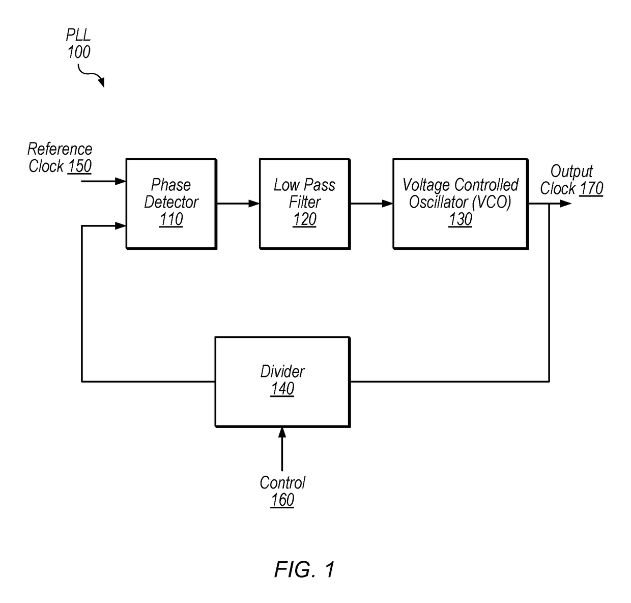
[0017]FIG. 1 is a block diagram illustrating an exemplary phase-locked loop (PLL) 100 according to some embodiments. PLLs are one example of feedback-controlled oscillators, but other types of feedback-controlled oscillators may be implemented in various embodiments, including frequency-locked loops (FLLs) for example. A feedback-controlled oscillator is an oscillator which is controlled, at least in part, based on a characteristic of its output. The oscillator portion of PLLs, for example, are controlled based on the phase of the oscillator output signal.

[0018]PLL 100, in the illustrated embodiment is configured to produce an output clock signal 170 based on two inputs: reference clock 150 and control signal 160. PLL 100, in the illustrated embodiment, includes phase detector 110, low pass filter 120, voltage-controlled oscillator (VCO) 130, and divider 140. In various embodiments, PLL 100 is configured to generate output clock 170 at a frequ...


PUM


Abstract

Techniques are disclosed relating to feedback-controlled oscillators (e.g., phase-locked loops) arranged in two or more levels. In some embodiments, in a relatively higher-frequency mode, a first level feedback-controlled oscillator provides reference signals to one or more second level feedback-controlled oscillators that in turn generate output clock signals to clock sequential circuitry. In some embodiments, in a relatively lower-frequency mode, the first level feedback-controlled oscillator bypasses the second level feedback-controlled oscillators and provides output clock signals directly to sequential circuitry (without using any intervening feedback-controlled oscillators).

Description

BACKGROUND[0001]Technical Field[0002]This disclosure relates generally to clocking circuitry and more specifically to feedback-controlled oscillators (e.g., phase-locked loops) arranged in two or more levels.[0003]Description of the Related Art[0004]Computer processing devices typically include sequential circuitry such as latches and flip-flops that are configured to perform various operations based on clock signal inputs. Driving clock signals to different portions of a circuit often consumes a significant portion of overall power consumption. As clock speed increases, reducing deviation from the desired clock periodicity (often referred to as “jitter”) in clock signals may become more important. Clock signals are typically controlled to a desired frequency using feedback-controlled oscillators, e.g., phase-locked loops (PLLs) or frequency-locked loops (FLLs). In some situations, multiple levels of feedback-controlled oscillators may be implemented to provide clock signals with lo...

Claims


Application Information

Patent Timeline
IPC IPC(8): H03L7/00H03L7/07H03L7/099
CPCH03L7/07H03L7/099H03L7/23
Inventor GULATI, MANURAMESH, SUHAS KUMAR SUVARNAMALLADI, VENKATA RAMANAHUANG, THOMAS H.NOTANI, RAKESH L.JETER, ROBERT E.HSIUNG, KAI LUN
Owner ALLLE INC
Why Eureka
Try Eureka