Auxiliary drive wheel-side differential unit for four-wheel drive vehicle

a technology of differential unit and side differential, which is applied in the direction of mechanical actuated clutches, interlocking clutches, etc., can solve the problems of differential gear unit, insufficient lubricating oil for gears, such as the pair of side gears and a pair of pinions, and achieve the effect of reducing the size and prolonging the stroke of the movable meshing member

Active Publication Date: 2017-07-04
JTEKT CORP
View PDF7 Cites 3 Cited by
  • Summary
  • Abstract
  • Description
  • Claims
  • Application Information

AI Technical Summary

Benefits of technology

[0008]The invention provides an auxiliary drive wheel-side differential unit for a four-wheel drive vehicle, which prevents a fully differential state of a differential gear unit in a disconnect mode.
[0010]According to the above aspect, The part of the intermeshing disconnect mechanism is provided between the ring gear and the cylindrical shaft of the differential case of the differential gear unit, and, in a disconnect mode in which the power transmission member is disconnected from the auxiliary drive wheels, the ring gear is disconnected from the differential case by the intermeshing disconnect mechanism. Thus, in the disconnect mode, a fully differential state of the differential gear unit is prevented.
[0011]In the above aspect, the separating mechanism may include first teeth, second teeth and a movable meshing member, the first teeth may be provided on the cylindrical ring gear, the second teeth may be configured to engage with the first teeth, the movable meshing member may be provided on an outer periphery of the cylindrical shaft so as to be non-rotatable and to move in a direction of the rotation axis. The actuator may be configured to move the movable meshing member to one of the connection position and the disconnection position by using an electromagnet. According to the above aspect, for example, in comparison with a configuration that a control coupling is provided between the ring gear and the differential gear unit, co-rotation of the cylindrical ring gear as a result of rotation of the differential case of the differential gear unit is prevented in the two-wheel drive mode.
[0012]In the above aspect, the actuator may include a spring, a first piston, a second piston, a holder, and a trip mechanism. The spring may be configured to urge the movable meshing member from the disconnection position toward the connection position. The first piston may be configured to be reciprocated by a predetermined stroke by using the electromagnet in the direction of the rotation axis. The second piston may be provided on the cylindrical ring gear so as to relatively rotate. The second piston may be moved by the first piston against an urging force of the spring, The holder may include multi-step latch teeth. The holder may be provided on the cylindrical ring gear so as to be relatively non-rotatable and non-movable in the direction of the rotation axis. The holder may be configured to latch the second piston, moved by the first piston, with any one of the multi-step latch teeth. The trip mechanism may be configured such that the first piston reciprocates for a predetermined number of times thereby the second piston moves the movable meshing member to the disconnection position against the urging force of the spring. The trip mechanism may be configured to unlatch the second piston when the number of times of reciprocating stroke exceeds the predetermined number of times, and the trip mechanism may be configured to allow the movable meshing member to move to the connection position under the urging force of the spring. According to the above aspect, for example, in comparison with a configuration that the movable meshing member is reciprocated by a predetermined stroke by attracting a movable piece by using the electromagnet, it is possible to suitably extend the stroke of the movable meshing member by using the trip mechanism.
[0013]In the above aspect, the auxiliary drive wheel-side differential unit may further include a synchronizer. The synchronizer may include a gear-side friction engagement member and a movable-side friction engagement member. The gear-side friction engagement member may be provided on the cylindrical ring gear so as to be relatively non-rotatable. The movable-side friction engagement member may be provided on the cylindrical shaft so as to be relatively non-rotatable and to move in the direction of the rotation axis together with the movable meshing member. The synchronizer may be configured to synchronize rotation of the movable meshing member with rotation of the ring gear by bringing the gear-side friction engagement member into sliding contact with the movable-side friction engagement member when the movable meshing member moves to a side of the connection position that is closest to the disconnection position before movement of the movable meshing member to the connection position. A part of the synchronizer may be arranged on the radially inner side of the cylindrical ring gear. According to the above aspect, because the part of the synchronizer is arranged on the radially inner side of the cylindrical ring gear, it is possible to suitably reduce the size of the auxiliary drive wheel-side differential unit in the direction of the rotation axis of the ring gear.

Problems solved by technology

Thus, there is an inconvenience that the differential gear unit that couples the axle, on which the control coupling is provided, is placed in a fully differential state during traveling for a long period of time.
Thus, if such a fully differential state continues, there is a possibility that lubricating oil that lubricates the gears, such as the pair of side gears and a pair of pinions, of the differential gear unit becomes insufficient because of rotation of the ring gear.

Method used


Image

  • Auxiliary drive wheel-side differential unit for four-wheel drive vehicle
  • Auxiliary drive wheel-side differential unit for four-wheel drive vehicle
  • Auxiliary drive wheel-side differential unit for four-wheel drive vehicle

Examples


Embodiment Construction

[0022]Hereinafter, embodiments of the invention will be described in detail with reference to the accompanying drawings. In the following embodiment, the drawings are modified or simplified where appropriate, and the scale ratio, shape, and the like, of each portion are not always drawn accurately.

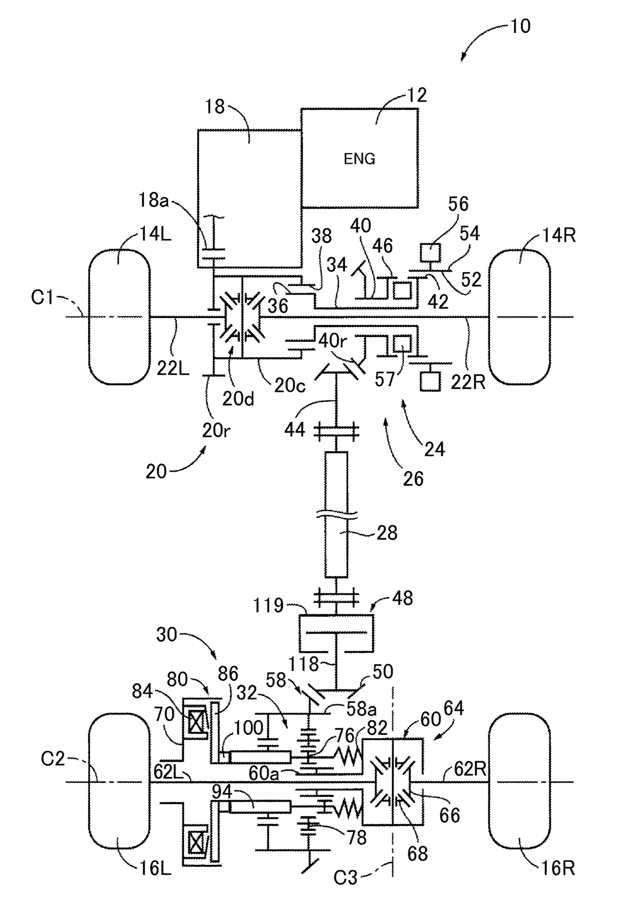
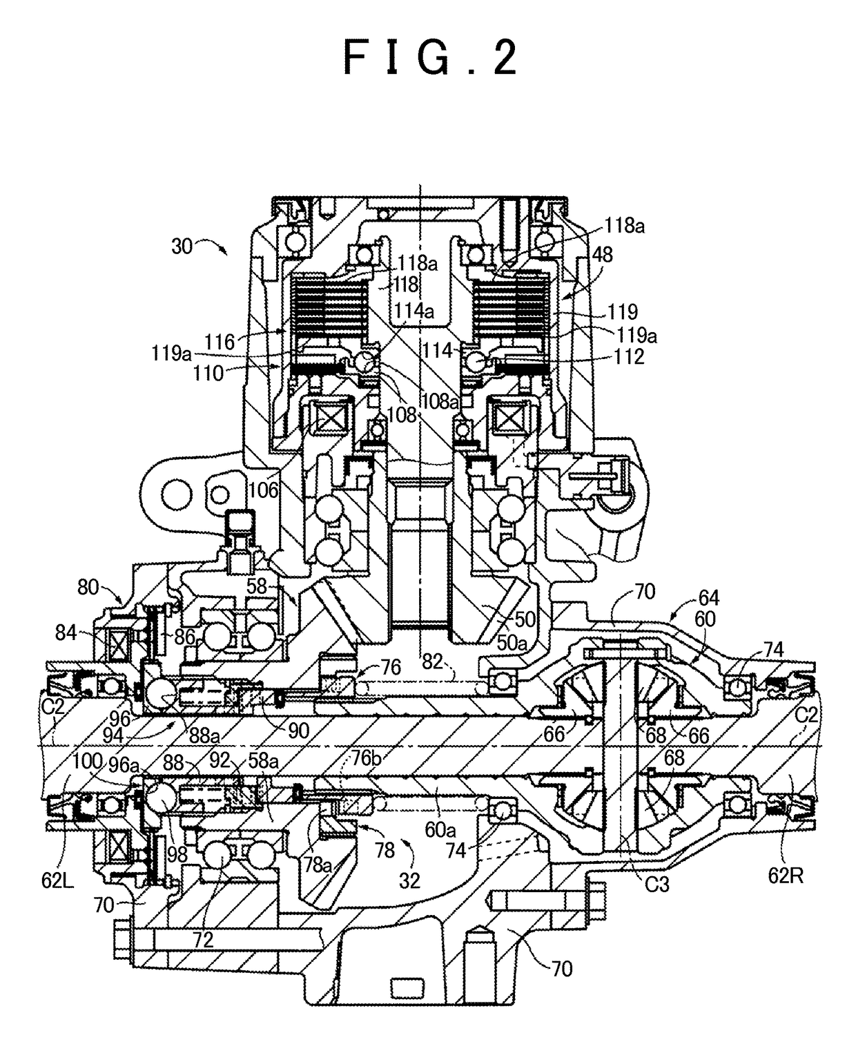
[0023]FIG. 1 is a skeletal view that schematically illustrates the configuration of a four-wheel drive vehicle 10 to which the invention is suitably applied. In FIG. 1, the four-wheel drive vehicle 10 includes an engine 12 as a driving source. The four-wheel drive vehicle 10 includes a four-wheel drive system that includes a first power transmission path and a second power transmission path. The first power transmission path transmits power of the engine 12 to right and left front wheels 14R, 14L (unless specifically distinguished from each other, referred to as front wheels 14) corresponding to main drive wheels. The second power transmission path transmits power of the engine 12 to right...


PUM


Abstract

A movable sleeve of a second clutch is provided between a cylindrical ring gear and a cylindrical shaft of a differential case of a differential gear unit. In a disconnect mode in which a propeller shaft is disconnected from rear wheels, the cylindrical ring gear is disconnected from the differential case by the movable sleeve of the second clutch. Thus, in the disconnect mode, a fully differential state of the differential gear unit is prevented.

Description

INCORPORATION BY REFERENCE[0001]The disclosure of Japanese Patent Application No. 2013-261873 filed on Dec. 18, 2013 including the specification, drawings and abstract is incorporated herein by reference in its entirety.BACKGROUND OF THE INVENTION[0002]1. Field of the Invention[0003]The invention relates to, in an auxiliary drive wheel-side differential unit for a four-wheel drive vehicle that includes a power transmission member configured to transmit driving force from a driving source to auxiliary drive wheels in a four-wheel drive mode and that disconnects the power transmission member from the auxiliary drive wheels in a two-wheel drive mode, a technique for preventing a fully differential state of a differential gear unit provided in the auxiliary drive wheel-side differential unit when the power transmission member is disconnected from the auxiliary drive wheels.[0004]2. Description of Related Art[0005]There is known a four-wheel drive vehicle in which a two-wheel drive mode ...

Claims


Application Information

Patent Timeline
Patent Type & Authority Patents(United States)
IPC IPC(8): B60K17/346B60K23/08F16D27/118F16D11/00F16D23/12
CPCF16D27/118B60K17/3462B60K23/0808F16D2011/004F16D2023/123
Inventor TAMOTO, HIDEKIYOSHIMURA, TAKAHIRO
Owner JTEKT CORP
Why Eureka
Try Eureka