
Wireless communication network using frequency conversion of MIMO signals

a wireless communication and mimo signal technology, applied in the field of communication networks, can solve the problems of inability to achieve significant increases in data rates, inability to justify the addition of infrastructure costs, and inapplicability of outdoor areas to unwanted restrictions of transmission capacity due to mimo signal correlation in parallel. , to achieve the effect of reducing the speed of the mobile umbrella cell, and reducing the number of data packets

Active Publication Date: 2017-06-20
ANDREW WIRELESS SYST GMBH +1
View PDF31 Cites 4 Cited by
  • Summary
  • Abstract
  • Description
  • Claims
  • Application Information

AI Technical Summary

Benefits of technology

The patent is about a way to prevent signals from being sent through a system and then bouncing back to interfere with other signals. This is done by using a special filter that adjusts the signal's transfer function to suppress any feedback. This approach is useful for improving the quality of communication signals.

Problems solved by technology

In supplying relatively large radio cells in the outdoor area, significant increases in the data rates can only be achieved with two antennas arranged to be cross-polar, particularly with a direct line of sight (LOS) between the communication partners.
The results achieved with other configurations (NLOS—Non Line Of Sight), particularly with more than two antennas, frequently do not justify the costs for the infrastructure becoming additionally necessary.
One main reason for these unsatisfactory results is based on the small angular spread and the resultant strong correlation of the communication signals of different antennas in the outdoor area.
The remaining ranges are utilized either only regionally, e.g. terrestrial television, only locally, e.g. in-house WLAN, or limited in time, e.g. radar, and thus very inefficiently.
Due to the fact that the MIMO signals are transmitted frequency-converted by utilizing free frequencies via the air interface, however, the unwanted restriction of the transmission capacity due to correlation of the MIMO signals transmitted in parallel is not applicable in the outdoor area.
With such a technology, a further impairment of the data throughput can be expected (apart from the unwanted restriction by correlation of the MIMO signals in the outdoor area).
This is because it has been found that the frequency offset increasing with increasing speed of the mobile umbrella cell additionally impairs the desired decorrelation of the equal-frequency MIMO signals due to Doppler shift.
Presently known methods for correcting this effect only allow a modulation rate of the mobile system.
However, the introduction of such terminals and such base stations is associated with a high cost expenditure and the establishment of an additional infrastructure.

Method used


Image

  • Wireless communication network using frequency conversion of MIMO signals
  • Wireless communication network using frequency conversion of MIMO signals
  • Wireless communication network using frequency conversion of MIMO signals

Examples


Embodiment Construction

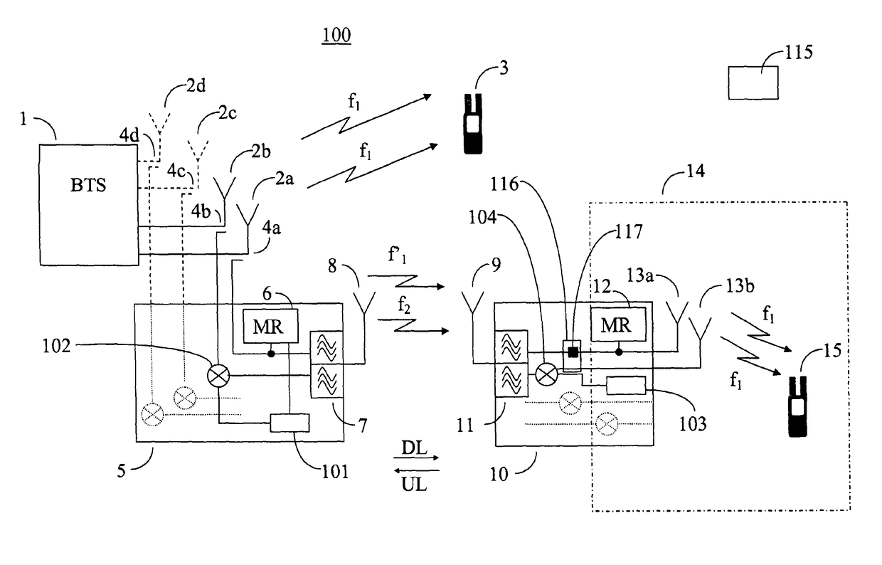
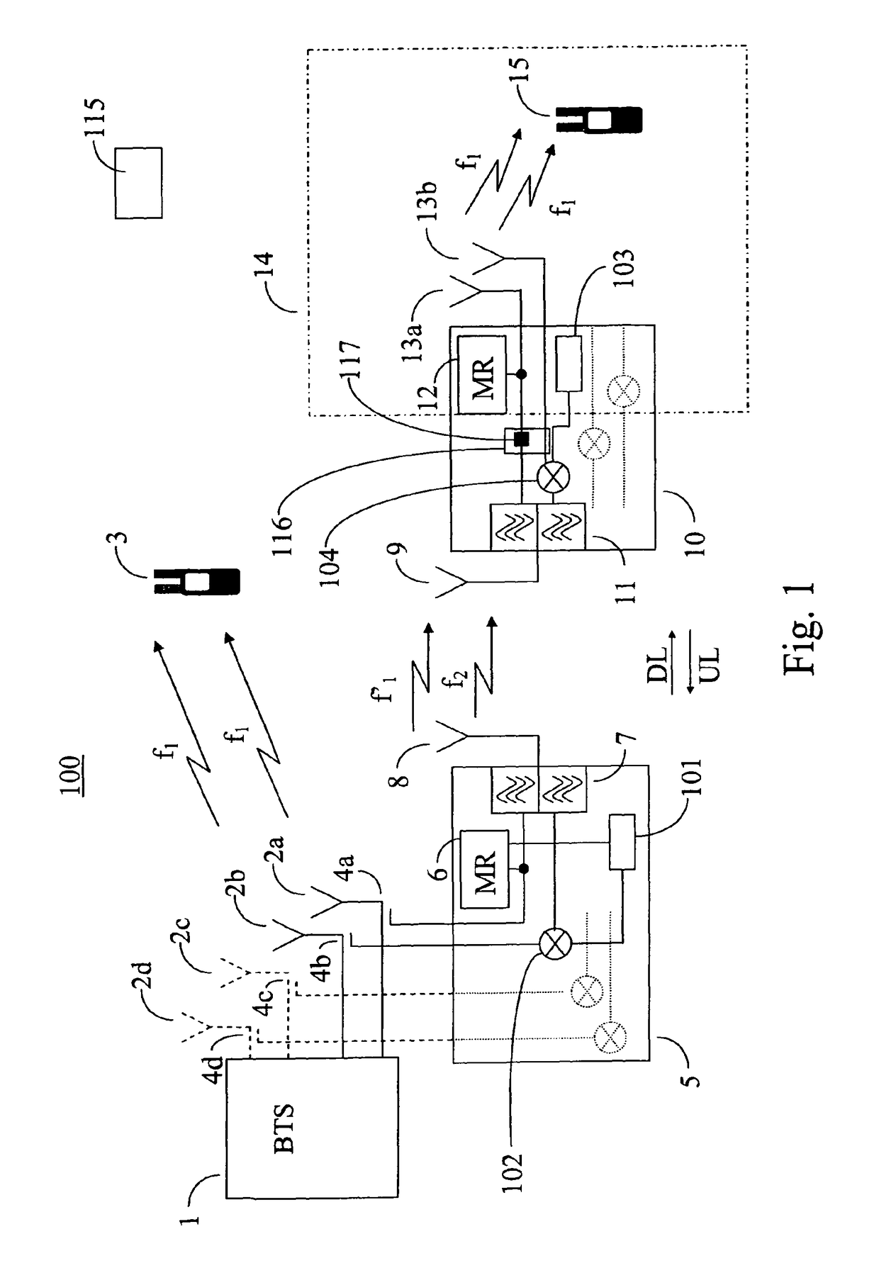
[0045]FIG. 1 diagrammatically shows a communication network 100 with a MIMO-capable base station 1, a MIMO-capable terminal 3, a MIMO-capable terminal 15 and two repeaters 5, 10. In this arrangement, the transmission path of the communication signals is shown in the downlink direction DL for the sake of clarity. The embodiments shown can be correspondingly transferred to the transmission of the communication signals in the uplink direction UL. The utilization of MIMO transmission techniques in the uplink direction UL is currently not a component of MIMO-capable mobile communication networks. However, the utilization of MIMO transmission techniques in the uplink direction UL will be a firm component of future revisions.

[0046]To utilize the MIMO transmission technique, the base station 1 and the terminals 3, 15 in each case have at least two antennas for the communication within a frequency band assigned for a mobile network. The corresponding two antennas 2a and 2b are identified for...


PUM


Abstract

Communication network (100) for wireless communication, comprising a base station (1, 16, 26), a wireless terminal (3, 15, 18, 25, 37) and at least one repeater (5, 10, 20, 28, 33) which is connected between the base station (1, 16, 26) and the wireless terminal (3, 15, 18, 25, 37), the base station (1, 16, 26) being configured for transmitting and receiving a communication signal on multiple information channels, the terminal (3, 15, 18, 25, 37) being configured for transmitting and receiving a communication signal on multiple information channels, and the repeater (5, 10, 20, 28, 33) being configured for receiving, passing through and retransmitting communication signals on multiple information channels, and contains a converting device (101, 103, 106, 110, 118) for frequency conversion of at least one information channel passed through, a test receiver (6, 12, 22, 34, 38) being additionally comprised which is configured for determining unused frequency ranges for wireless communication, the test receiver (6, 12, 22, 34, 38) being connected to the converting device (101, 103, 106, 110, 118) of the repeater (5, 10, 20, 28, 33), the converting device (101, 103, 106, 110, 118) being configured for carrying out the frequency conversion in at least one communication direction (UL, DL) to a frequency from the unused frequency ranges, and the repeater (5, 10, 20, 28, 33) being configured for transmitting the communication signal wirelessly with the at least one frequency-converted information channel in the at least one communication direction.

Description

RELATED APPLICATIONS[0001]This application is a National Application of, and claims priority to, International Publication Number WO2013 / 087166, filed Dec. 6, 2012, entitled “WIRELESS COMMUNICATIONS NETWORK”, which claims priority to German Application Serial No. DE 10 2011 120827.9, filed Dec. 13, 2011, entitled “WIRELESS COMMUNICATIONS NETWORK”, which applications are each incorporated herein by reference in their entireties.BACKGROUND AND DESCRIPTION OF THE INVENTION[0002]The invention relates to a communication network for wireless communication, comprising a base station, a wireless terminal and at least one repeater which is connected between the base station and the wireless terminal. In this arrangement, the base station and the terminal are configured for transmitting and receiving a communication signal on multiple information channels. The repeater is configured for receiving, passing through and retransmitting communication signals on multiple information channels. The c...

Claims


Application Information

Patent Timeline
Patent Type & Authority Patents(United States)
IPC IPC(8): H04B7/145H04B7/0413H04B7/155H04W72/04H04B7/04H04B7/26H04L69/14
CPCH04B7/145H04B7/0413H04B7/15542H04W72/0453H04B7/2606
Inventor BRAZ, OLIVERDUSSMANN, ALFONSTARLAZZI, LUIGIHAUSTEIN, THOMASWIRTH, THOMASWIERUCH, DENNISJONDRAL, FRIEDRICHJAKEL, HOLGER
Owner ANDREW WIRELESS SYST GMBH
Learn More