
Cable lacing tie devices and methods of using the same

a technology of tie-ins and cables, which is applied in the field of tie-ins and devices for holding objects together, can solve the problems of reducing the strength of the strap, increasing the tendency of the strap to tear through, and generally not being able to closely hug irregular or rectangular shapes

Active Publication Date: 2017-06-20
DANIELS MFG CORP
View PDF62 Cites 15 Cited by
  • Summary
  • Abstract
  • Description
  • Claims
  • Application Information

AI Technical Summary

Benefits of technology

The cable lacing tie device is designed to withstand high temperatures and other extreme conditions. It is made from lightweight materials, which allows for weight savings compared to plastic cable ties. The device's head assembly provides easy installation with minimal force required. Overall, the cable lacing tie device provides a fast and secure method for cable lacing.

Problems solved by technology

However, such a barb or knife like strap piercing element is usually destructive to the strap when it cuts or bites into the strap, permanently reducing the strength of the strap and increasing the tendency for the strap to tear through.
However, in these instances, the cut section of the molded plastic strap that protrudes from the buckle can present an undesirable, fairly sharp obstruction that may result in abrasion problems with respect to adjacent wire bundles, and may be problematic if one is attempting to pull the wire bundle through an aperture, such as a panel opening.
It should be noted that another drawback of molded plastic cable ties is that, due to their relative rigidity, they generally are not capable of closely hugging irregular or rectangular shapes, as may occur when bundling wires, wire harnesses or cables, or connecting them to other structures.
In use, a cable tie can be subjected to elevated temperatures, such as for instance in the aerospace environment, which may reach as high as 400° F. These elevated temperatures can cause a common cable tie, which is typically molded from thermoplastic material, such as nylon, to creep or lose structural integrity.
The locking element or pawl generally will be constructed to be deflectable, so as to reduce the strap insertion force, but this also compromises the ability to retain the strap, especially at high temperatures.
Cable ties that have a separately provided metal locking element or pawl usually are intended to provide for increased retention, even at elevated temperatures, but these structures typically require higher insertion forces when passing over the metal element.
Materials such as aramid fiber provide good tensile strength, while being non-flammable, highly resistant to fluids and lubricants, and able to perform in extreme temperature environments, such as from approximately −65° F. to 500° F. However, cable lacing has drawbacks in that the cable lacing tape typically is tied by hand in a costly, labor-intensive, and time-consuming process.

Method used


Image

  • Cable lacing tie devices and methods of using the same
  • Cable lacing tie devices and methods of using the same
  • Cable lacing tie devices and methods of using the same

Examples


Embodiment Construction

[0020]The following description of example methods and apparatus is not intended to limit the scope of the description to the precise form or forms detailed herein. Instead the following description is intended to be illustrative so that others may follow its teachings.

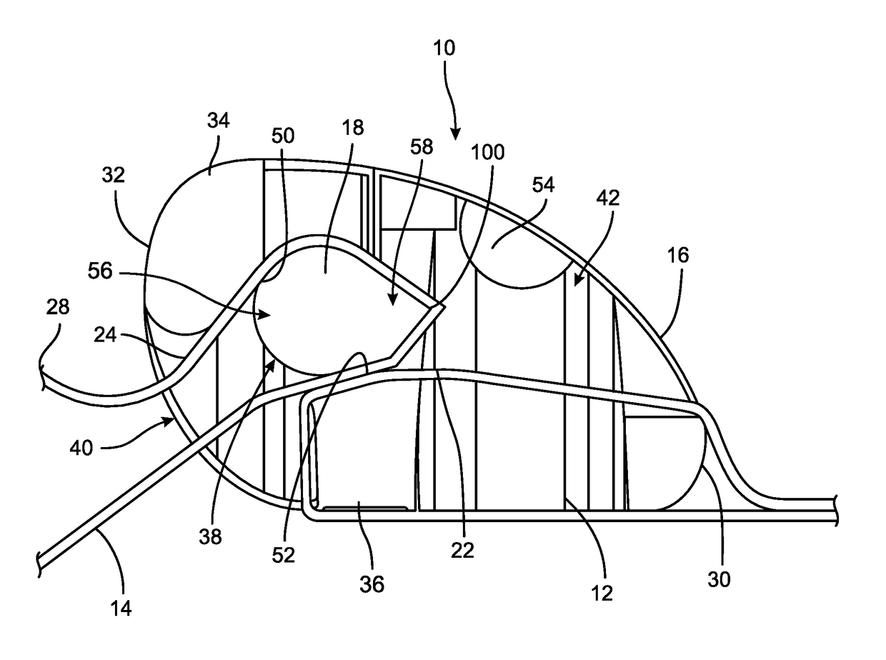
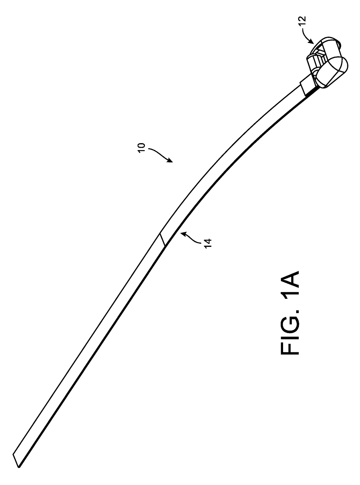
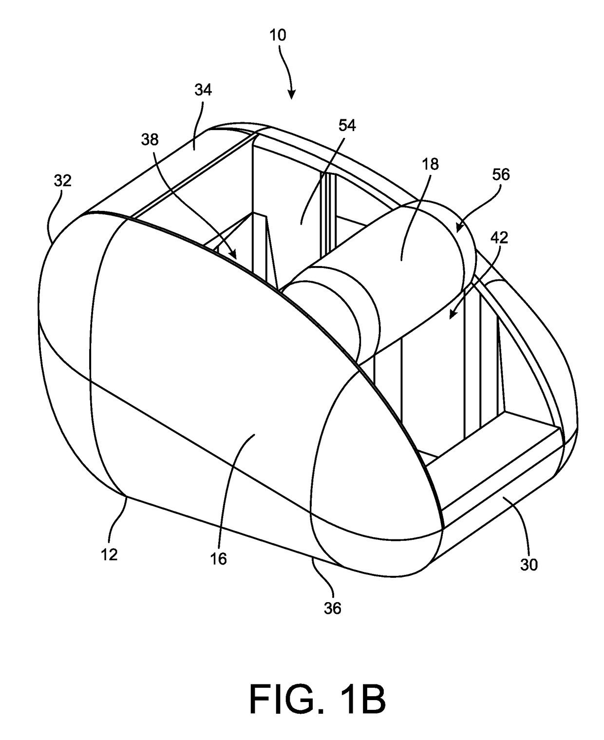
[0021]The present disclosure provides cable lacing tie devices for holding together a plurality of objects, such as objects of similar or different sizes that are to be gathered and held together at one or more predetermined locations, such as points along a group of wires, wiring harnesses, or cables that are gathered together to form a bundle. The disclosed cable lacing tie devices generally comprise a head assembly and a length of cable lacing tape, such as for instance a braided filament element. A first portion, such as a first end of the length of cable lacing tape, may be retained by the head assembly. In one example, the cable lacing tape is routed through, or otherwise connected to or molded within a body of ...


PUM

PropertyMeasurementUnit
temperaturesaaaaaaaaaa
lengthsaaaaaaaaaa
structuresaaaaaaaaaa

Abstract

A cable lacing tie device includes a head assembly and a cable lacing tape. The head assembly being configured to retain a first portion of the cable lacing tape within the head assembly and having a length of the cable lacing tape extending from the head assembly. The head assembly further adapted to retain a second portion of the cable lacing tape extending from the head assembly. The methods of using the cable lacing tie devices include retaining a first portion of a cable lacing tape in a head assembly, looping the cable lacing tape around a plurality of objects, and retaining a second portion of the cable lacing tape within the head assembly.

Description

CROSS REFERENCE TO RELATED APPLICATION[0001]This application is a continuation of U.S. patent application Ser. No. 14 / 223,685 filed Mar. 24, 2014, entitled “Cable Lacing Tie Devices and Methods of Using the Same” and incorporated herein by reference in its entirety.FIELD OF THE DISCLOSURE[0002]The present description relates generally to devices and methods for holding objects together and more particularly to cable lacing tie devices and methods of using the same.BACKGROUND OF RELATED ART[0003]Individual wires, wire harnesses, or cables having two or more wires or strands are customarily grouped and held adjacent to each other at various points along their lengths by use of cable ties or cable lacing tape. For example, it may be desirable to hold together two or more wires, wire harnesses, cables or other objects, or connect such objects to other structures. In these instances, cable lacing tie assemblies may be used to help ensure the safety and durability of the various component...

Claims


Application Information

Patent Timeline
Patent Type & Authority Patents(United States)
IPC IPC(8): B65D63/10B65D63/00F16L3/22F16L3/23H02G3/32
CPCB65D63/1018B65D63/00B65D63/10F16L3/22F16L3/23H02G3/32Y10T24/14Y10T24/142Y10T24/1414Y10T29/49826B65D63/16B65D63/1027
Inventor ZANTOUT, ALAN E.SUTTER, ROBERT W.WEIBY, MICHAELDAVIDSON, JAMES
Owner DANIELS MFG CORP
Learn More