Method and related equipment for sending signaling
a signaling and equipment technology, applied in the field of communication, can solve problems such as user experience deterioration, and achieve the effect of improving user experien
- Summary
- Abstract
- Description
- Claims
- Application Information
AI Technical Summary
Benefits of technology
Problems solved by technology
Method used
Image
Examples
first embodiment
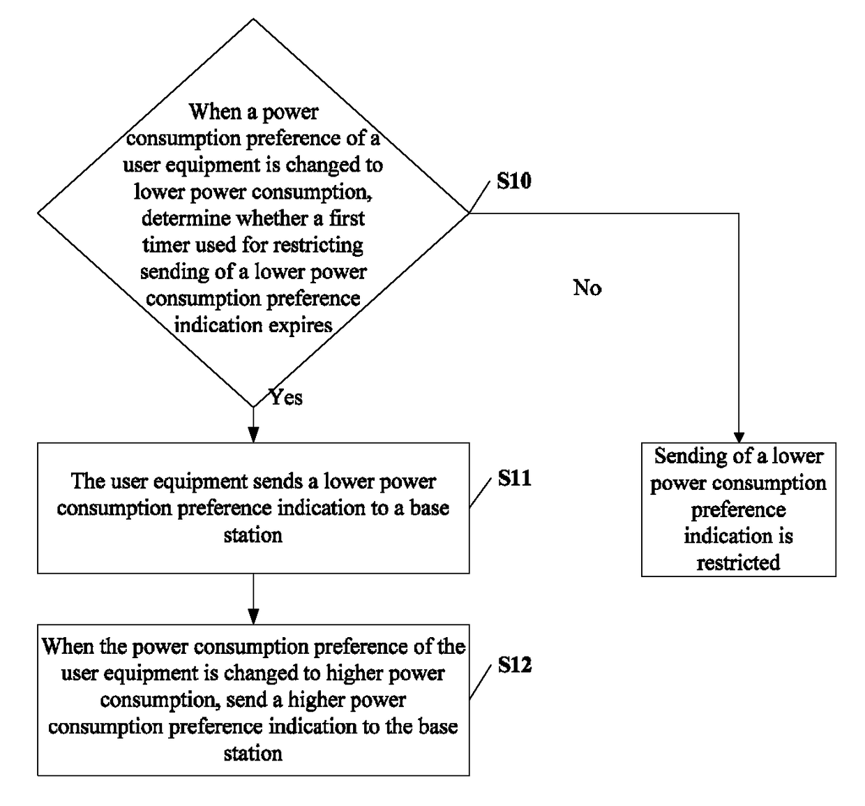
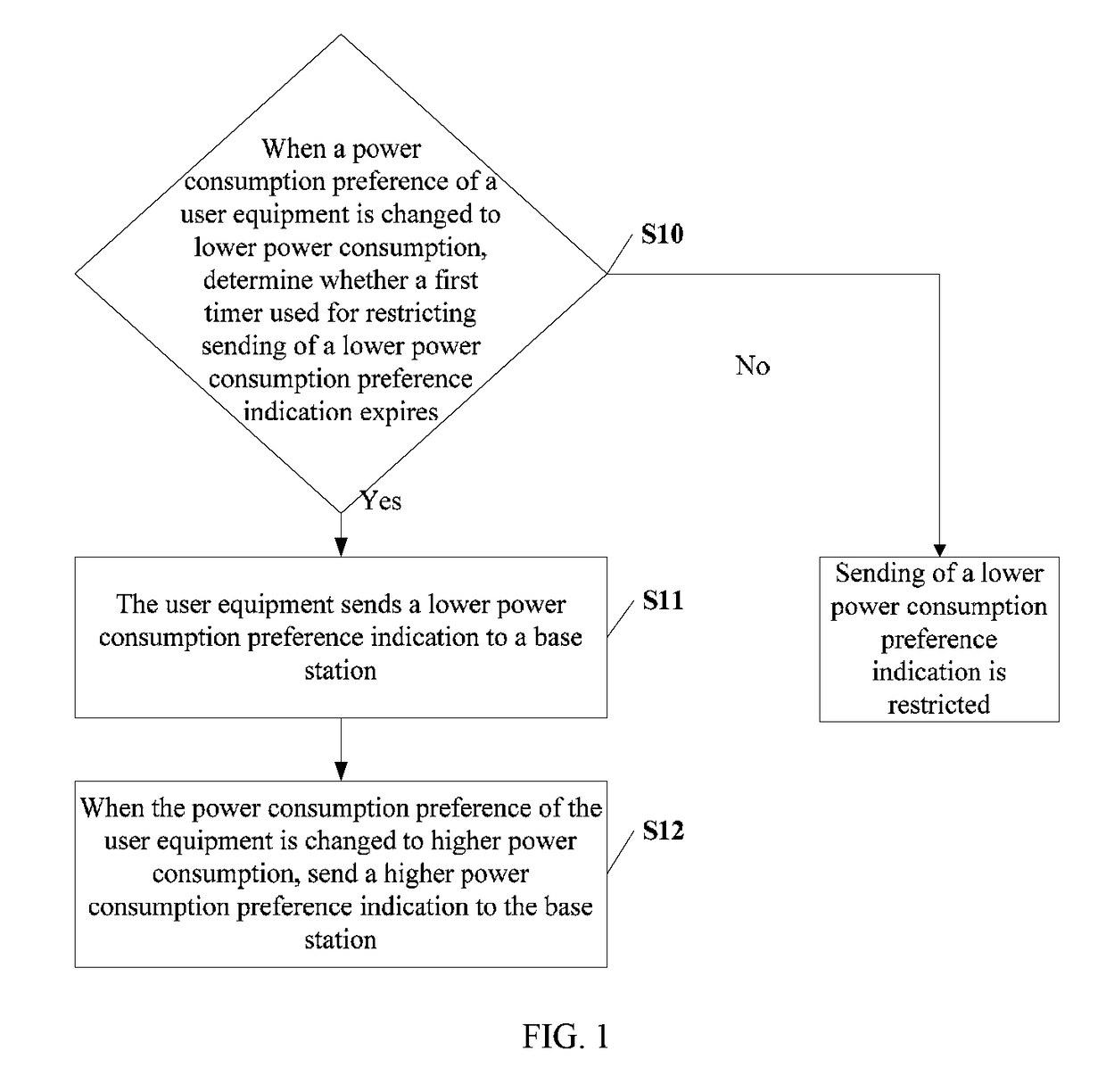
[0029]FIG. 1 is a schematic flowchart of a method for sending signaling according to the present invention. As shown in FIG. 1, the method may include:
[0030]Step S10: When a power consumption preference of a user equipment is changed to lower power consumption, determine whether a first timer used for restricting sending of a lower power consumption preference indication expires, and if a determination result is yes, perform step S11.
[0031]Step S11: The user equipment sends a lower power consumption preference indication to a base station.
[0032]Step S12: When the power consumption preference of the user equipment is changed to higher power consumption, send a higher power consumption preference indication to the base station.
[0033]In some feasible implementation manners, step S10 and step S12 may be performed in any sequence, that is, the power consumption preference of the user equipment is first changed to higher power consumption and then changed to lower power consumption.
[0034]...
second embodiment
[0177]FIG. 6 is a schematic structural diagram of a user equipment according to the present invention. As shown in FIG. 6, the user equipment of the present invention may include an indication sending module 800, a first controlling module 801, and a third controlling module 803.
[0178]The indication sending module 800 is configured to send a power consumption preference indication to a base station, where the power consumption preference indication includes a lower power consumption preference indication or a higher power consumption preference indication.
[0179]The first controlling module 801 is configured to determine, when a power consumption preference of the user equipment is changed to lower power consumption, whether a first timer used for restricting sending of a lower power consumption preference indication expires, and if a determination result is yes, notify the indication sending module 800 to send a lower power consumption preference indication to the base station.
[0180...
fourth embodiment
[0255]FIG. 8 is a schematic structural diagram of a user equipment according to the present invention. As shown in FIG. 8, the user equipment of this embodiment may include an indication sending module 1000, a first controlling module 1001, a second controlling module 1002, a third controlling module 1003, a configuration receiving module 1004, and a third timer managing module 1005, where at least one of the second controlling module 1002 and the third controlling module 1003 exists in the user equipment of the present invention.
[0256]The indication sending module 1000 is configured to send a power consumption preference indication to a base station, where the power consumption preference indication includes a lower power consumption preference indication or a higher power consumption preference indication.
[0257]The first controlling module 1001 is configured to determine, when a power consumption preference of the user equipment is changed to lower power consumption, whether a fir...
PUM
 Abstract
Description
Claims
Application Information
 - R&D
- Intellectual Property
- Life Sciences
- Materials
- Tech Scout
- Unparalleled Data Quality
- Higher Quality Content
- 60% Fewer Hallucinations
Browse by: Latest US Patents, China's latest patents, Technical Efficacy Thesaurus, Application Domain, Technology Topic, Popular Technical Reports.
© 2025 PatSnap. All rights reserved.Legal|Privacy policy|Modern Slavery Act Transparency Statement|Sitemap|About US| Contact US: help@patsnap.com


