
Conveyor roller with integral clutch

a conveyor and roller technology, applied in the direction of roller-ways, transportation and packaging, etc., can solve the problems of difficult operation, difficult operation, and high cost of traditional accumulator lines that use a single start and stop mechanism, and achieve the effect of convenient and efficient operation, cost-effective, reliable, and convenient and efficient operation

Active Publication Date: 2017-06-13
MHS CONVEYOR CORP
View PDF42 Cites 6 Cited by
  • Summary
  • Abstract
  • Description
  • Claims
  • Application Information

AI Technical Summary

Benefits of technology

The system provides a cost-effective and reliable solution for accumulator conveyor systems by minimizing wear on motors and drive systems, allowing for efficient and controlled slip, reducing operational costs, and maintaining consistent torque application across rollers, even under heavy loads.

Problems solved by technology

With heavier loads such as beverages, which have a high weight in a small space, traditional accumulator lines that use a single start and stop mechanism are expensive, difficult to properly operate and have problematic operational considerations due to the dense packing of heavy loads on most accumulator conveyor systems.
More specifically, a long row of heavy loads, such as beverages, when tightly packed that must be stopped and started over and over, sometimes moving precisely only a single load forward or onto an intersecting or main conveyor segment, requires substantial force to start and stop and the start and stop mechanisms must be robustly built to take a lifetime of stops and starts without breakdown, which results in expensive mechanisms.
As such, it would be desirable to space the loads sufficiently apart; however, in many accumulator conveyor systems, the loads are packed as tightly as possible to maximize live storage on the conveyor system, which creates operational difficulties in efficiently and consistently stopping and starting in a reliable manner.
This can be extremely hard on the motor as well as the drive connection between the rollers and motor, particularly when the loads are densely packed on the system without gaps, and are a heavy dense material, such as beverages, laundry detergent, and metal hardware.
In addition, accumulator conveyor systems are generally price-sensitive and the addition of cost to any one area generally must be offset by a reduction in price on other parts of the conveyor system.
Therefore, it is difficult to use more expensive rollers or drive systems, to offset the extreme wear caused by the heavy densely packed loads.
While some manufacturers have proposed expensive clutches attached to the motor, in addition to problems with price sensitivity, these clutches have particular problems with starting and stopping the motor, such as for heavier loads excessive wear and tear which may cause shortened life expectancy, or may require more robust clutch systems that are substantially more expensive.
In addition, the motor, even if a clutch is used to protect the drive system between the clutch and each roller, may experience wear.
While some manufacturers have attempted to clutch individual rollers for larger pallet conveyor systems, these clutched rollers are extremely large and to date have been too expensive and too large to be practical in most settings other than pallet conveyors.
As such, not only has the cost, but also their size prevented them from being used in most package and beverage conveyor systems.
Any higher forward pressure and the system will not allow for controlled slip situations, and may damage the system or loads.
To date no system efficiently and in a reliable manner applies a light enough load for under fifty pound packages or loads on the system when the clutch system is coupled to or within each roller.
More specifically, a light load applied by each roller has been difficult to consistently achieve with each roller applying less than 5 lbs. on average, preferably less than 2 lbs., and in many instances well under a pound of force, before slip occurs within the roller and not between the roller and the load.
In addition, current clutches attached to each roller are not cost effective when compared to single clutch systems, which include the above identified problems.

Method used


Image

  • Conveyor roller with integral clutch
  • Conveyor roller with integral clutch
  • Conveyor roller with integral clutch

Examples


Embodiment Construction

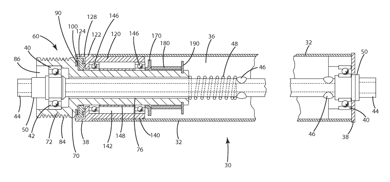
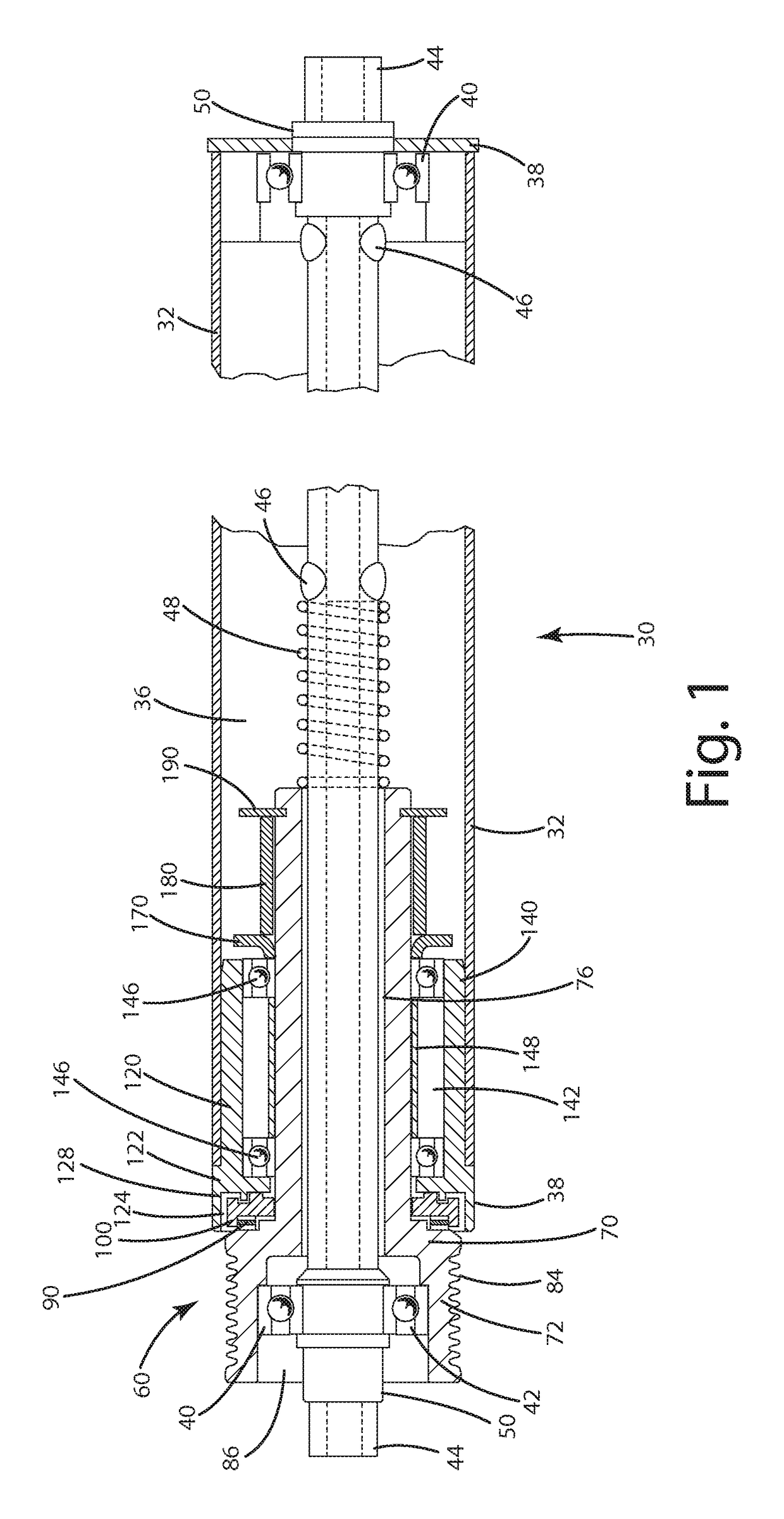
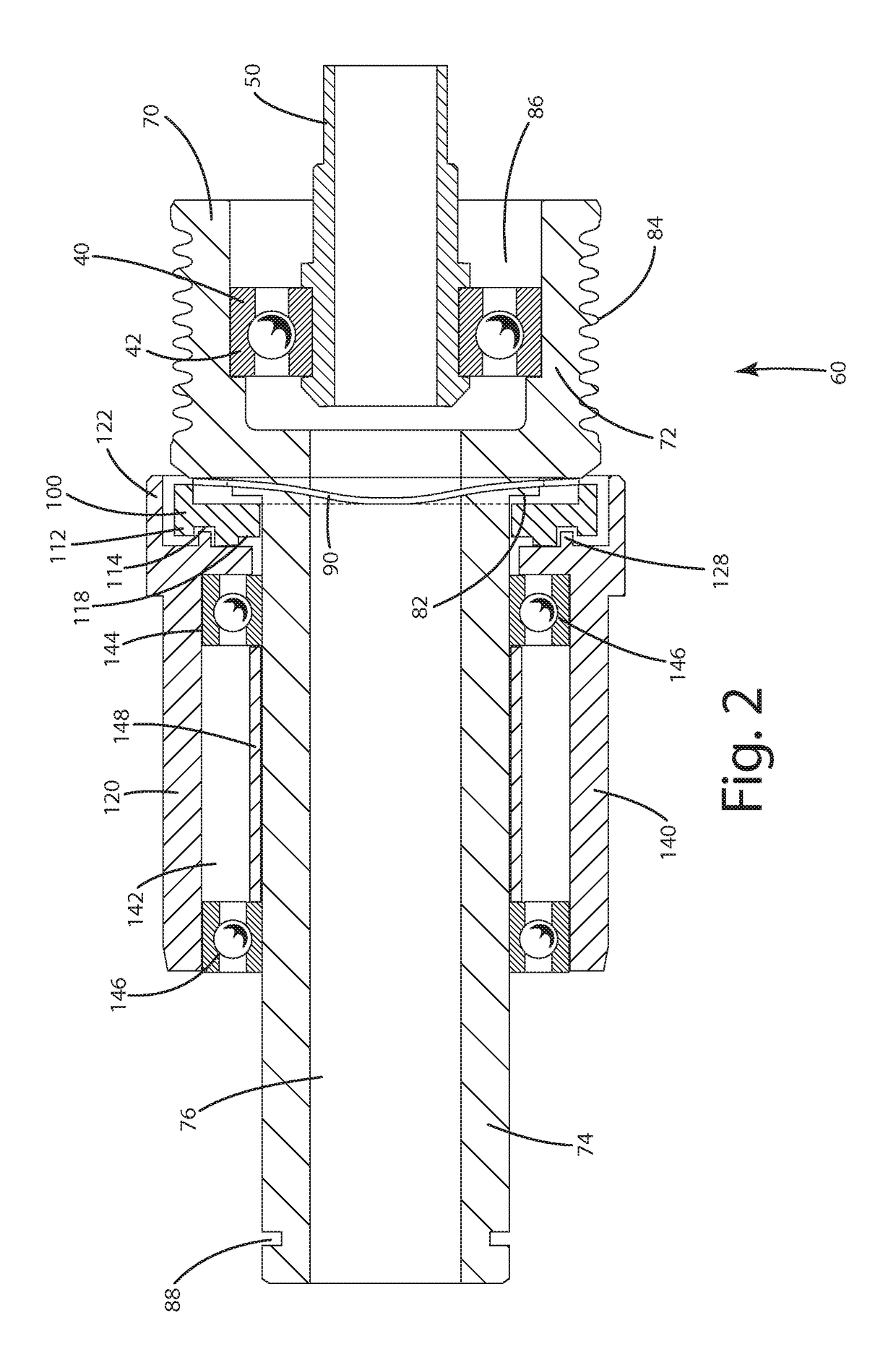
[0031]As illustrated in FIGS. 10 and 11, the present invention generally includes a roller bed conveyor system 10, typically for use with an accumulator conveyor. The conveyor system 10 of the present invention may be made in practically any desired configuration by combining straight segments, curved segments, intersections, ramped sections, and any other desirable segments in a variety of configurations with a variety of operational components, such as sorters, accumulators, transfers and / or diverters, as desired by the needs of the user. Accumulator conveyors are particularly useful when individual runs having a single product feed onto a main run in controlled fashion to allow automated sorting of a variety of products into a single order or destination. Each run may be made up of one or more desired segments. A single order may include a number of items going to the same destination, or same route or same truck, wherein the items may differ. For example, an order having forty t...


PUM


Abstract

A material handling system have the ability for the rollers to slip relative to the drive system, such as a roller bed conveyor used an accumulator conveyor system. The rollers include a slip assembly with a clutch surface, wherein the tube of the roller is configured to act as a heat sink.

Description

CROSS-REFERENCE TO RELATED APPLICATIONS[0001]This U.S. Patent Application claims the benefit of U.S. Provisional Patent Application Ser. No. 61 / 874,559 filed Sep. 6, 2013 entitled “Conveyor Roller With Integral Clutch,” the entire disclosure of the application being considered part of the disclosure of this application, and hereby incorporated by reference.BACKGROUND OF THE INVENTION[0002]1. Technical Field[0003]The present invention generally relates to a material handling system and more particularly, to a roller bed conveyor, such as an accumulator conveyor system, wherein limited and controlled slip between the roller surface and drive system is desired.[0004]2. Related Art[0005]Roller conveyors are commonly found in a variety of manufacturing, distribution and other warehouse facilities. Most roller conveyor systems include a variety of straight and curved segments configured to allow products, individually or packaged together, to travel through a facility, past various operat...

Claims


Application Information

Patent Timeline
Patent Type & Authority Patents(United States)
IPC IPC(8): B65G13/07B65G13/06B65G13/02B65G13/073
CPCB65G13/073B65G13/07
Inventor WALLACE, MATTHEW EARL
Owner MHS CONVEYOR CORP
Learn More