
Drive system for curved roller conveyor segments

a technology of curved segments and drive systems, which is applied in the direction of conveyors, roller-ways, transportation and packaging, etc., can solve the problems of complex electronic clutches, difficult to have the rollers in the curved segment accumulate in sequence, and the drive system for curved segments is traditionally more complex and expensive than the drive system, so as to achieve easy and efficient transfer of the ability to turn the rollers, the effect of cost-effective, efficient and reliabl

Active Publication Date: 2014-07-01
MHS CONVEYOR CORP
View PDF47 Cites 14 Cited by
  • Summary
  • Abstract
  • Description
  • Claims
  • Application Information

AI Technical Summary

Benefits of technology

The invention is a drive system for curved segments of roller conveyors that allows for the transfer of power from a straight segment to an adjacent curved segment in a cost-effective, efficient, and reliable manner. This system can be used with an accumulating conveyor, making it a very reliable and efficient conveyor system. The invention allows for easy and efficient transfer of the ability to turn the rollers from a driven straight segment to a slave curved segment.

Problems solved by technology

The curved segments of roller conveyors and in particular, the drive system for curved segments is traditionally more complex, difficult, and expensive than drive systems for similar straight segments.
In the curved segments, it is particularly difficult to have the rollers in the curved segment to accumulate in sequence with the straight conveyor it is feeding because the drive system for the curved conveyor segment is required to be of a different or additional drive system than the adjacent straight conveyor segment.
The drive system for curved segments in prior art systems employ complex electronic clutches, sophisticated pneumatic circuits or expensive motorized roller solutions that drop the drive off the curved segment in sequence with the adjacent straight conveyor.
One major issue with using O-rings to power adjacent rollers is that they are not an efficient transfer of power, and typically only two to three and at most, four to six adjacent rollers may be powered before the system is incapable of efficiently transferring the loads.
In addition, V-belts and O-rings quickly wear out due to the frictional load, especially if a roller stops rotating for any reason.
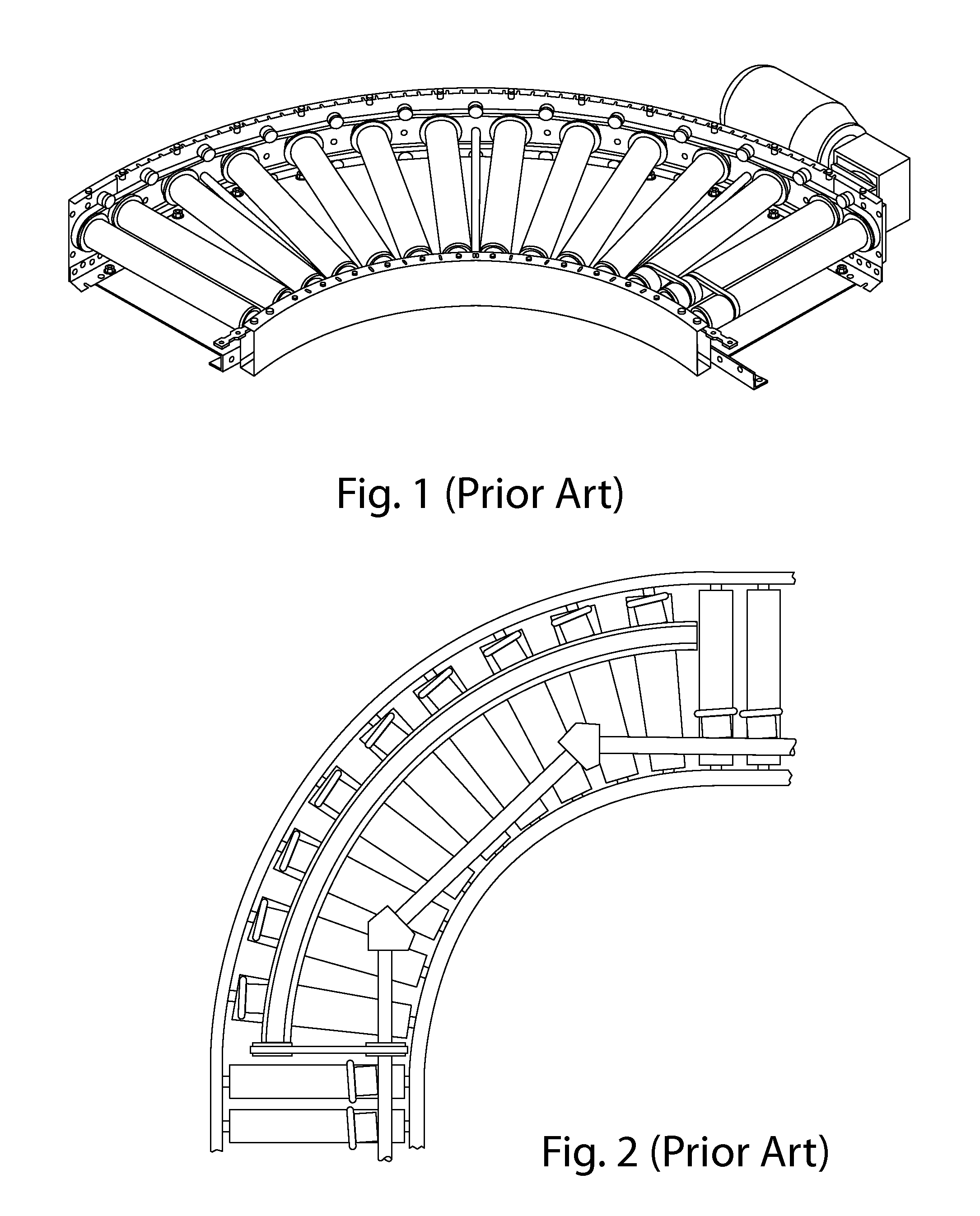
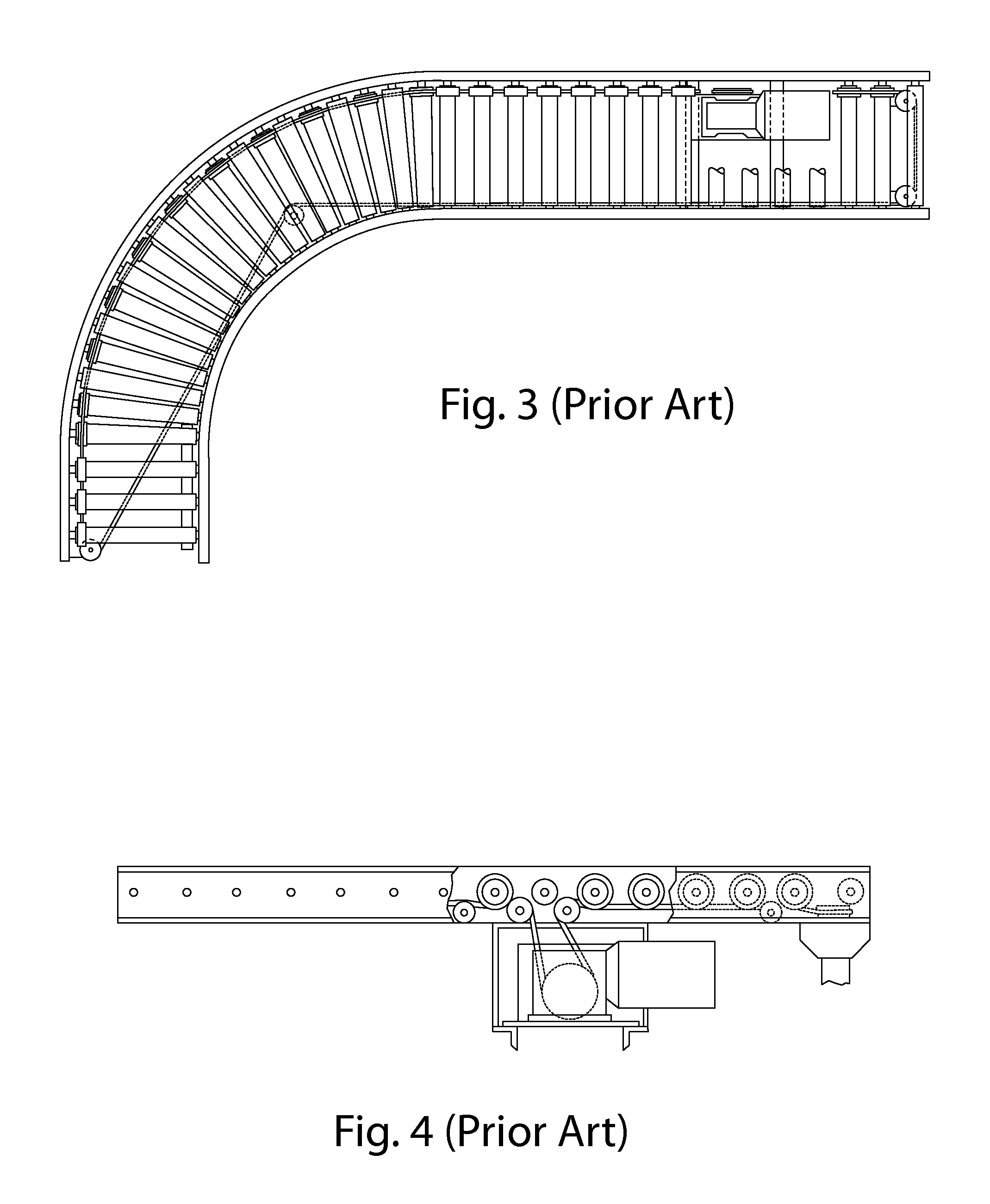
As illustrated in FIGS. 1-4, a variety of expensive and less efficient drive systems have been proposed to provide drive to the individual rollers on a curved roller conveyor segment.
When the curved roller conveyor segment is used in an accumulation conveyor, where it is desirable to start and stop the curved segments independent of other sections, special expensive mechanisms must be used such as a separate motor to drive the curved segment or clutches to selectively transfer power from the straight segment to the curved segment.
The first downside to the system illustrated in FIG. 1 is that it requires an independent motor, which is expensive and increases the product cost.
Installation costs are also increased as power must be run to each motor location.
Conveyor systems requiring a separate motor and therefore separate electric power connections are more difficult to reconfigure due to the requirement for moving the electric motor and associated power connections.
In addition, the elongated continuous V-belts are typically expensive as changes in radius, length, and degree of curve all change the length of the required belt which may in turn require the system to use numerous custom sized belts.
Another problem is that the curve of the conveyor segment may create additional wear on the continuous V-belt by each pulley, as each pulley has an axis that is not aligned with adjacent pulleys.
Another downside to using a continuous V-belt on a curved section is that if a roller or rollers stop turning, it may cause the V-belt to also stop, while the motor and associated drive pulley continue spinning, creating localized wear and heat, which significantly shortens the life of the V-belt.
In regards to FIG. 2, some manufactures, to avoid issues with separate motors for curved segments have proposed drive shafts with universal joints and individual drive rollers frictionally engaging at least some of the load bearing rollers, all of which significantly increase product cost and are difficult to and expensive to maintain.
In some instances, a complicated system having a transfer belt and short curved drive belt segments are used.
These customized belts may cause difficulty for the operators of the conveyor system in ordering the proper belt in the correct radius and length as well are difficult to install properly so they track as desired.
The drive shafts, universal joints, customized belts, and secondary friction drive rollers all create a very expensive drive system as well as increased installation costs.
The long V-belts may experience many of the problems listed above.
All of the above illustrated systems include drawbacks that reduce the reliability, longevity, or increase the cost of the drive system for the curved conveyor segments as well as installation and later reconfiguration costs.
Furthermore, the above described systems may include specialized belt lengths that may be difficult to easily order in a standardized size or may be extremely difficult to repair.
For example, if the elongated V-belt in FIG. 3 breaks, it is difficult to quickly and efficiently repair the system.

Method used


Image

  • Drive system for curved roller conveyor segments
  • Drive system for curved roller conveyor segments
  • Drive system for curved roller conveyor segments

Examples


Embodiment Construction

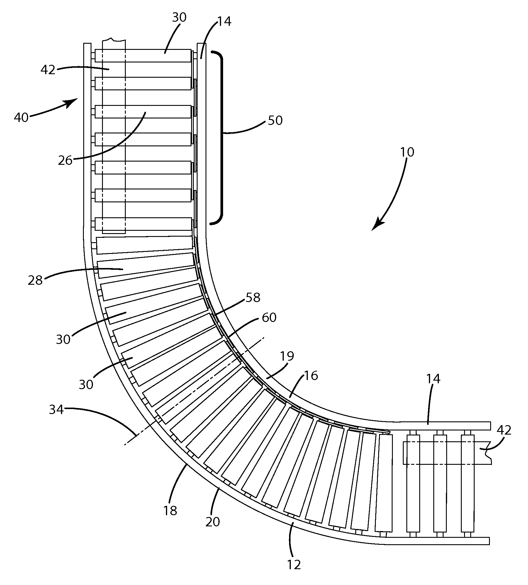
[0036]The present invention is generally directed to a conveyor system 10 and more specifically to a roller bed conveyor system, and yet more specifically to a drive system 20 for an accumulator conveyor system 10. The conveyor system 10 generally includes a structural support assembly 12 including supporting legs (not shown) and elongated frames 20 running in the direction of travel of the loads. The frames 20 are located on each side and support and properly space the individual rollers 30 that form the roller bed and rotate about an operational axis 29. As illustrated in the Figures, the frames 20 may be straight in certain segments as well as curved in others.

[0037]In the present invention, the conveyor system 10, structural support assembly 12 and associated frames 20 may be made in any size, shape, and configuration such as having various lengths and radii to transport loads along the desired paths and to the desired locations. The conveyor system 10 is specifically configured...


PUM


Abstract

A drive system for curved segments of roller conveyors and more specifically to a cost-effective, efficient, and reliable system of transferring power from a straight segment to an adjacent segment.

Description

CROSS REFERENCE TO RELATED APPLICATIONS[0001]This U.S. Utility patent application claims the benefit of U.S. Provisional Application Ser. No. 61 / 608,154 filed Mar. 8, 2012, the entire disclosure of the application being considered part of the disclosure of this application and hereby incorporated by reference.BACKGROUND OF THE INVENTION[0002]1. Technical Field[0003]The present invention relates to a drive system for curved segments of roller conveyors, and more specifically to cost-effective, efficient, and reliable systems of transferring power from a straight segment to an adjacent curved segment of an accumulator conveyor system.[0004]2. Related Art[0005]Roller conveyors are commonly found in a variety of a manufacturing, distribution, and warehouse facilities. Most roller conveyor systems include a variety of straight and curved segments configured to allow products, individually or packaged together, to wind their way through a facility past various operations and to various de...

Claims


Application Information

Patent Timeline
Patent Type & Authority Patents(United States)
IPC IPC(8): B65G13/08
CPCB65G13/08B65G13/00B65G13/04
Inventor WALLACE, MATTHEW, EARL
Owner MHS CONVEYOR CORP
Learn More