Clamp with ceramic electrode

a technology of ceramic electrodes and clamping rods, which is applied in the direction of electrostatic holding devices, manufacturing tools, and solventing apparatuses, can solve the problems of complex production of holding apparatuses, and achieve the effects of reducing the clamping voltage, simplifying production, and avoiding the disadvantages of conventional techniques

Active Publication Date: 2017-06-06
ASML NETHERLANDS BV
View PDF24 Cites 2 Cited by
  • Summary
  • Abstract
  • Description
  • Claims
  • Application Information

AI Technical Summary

Benefits of technology

[0006]The objective of the invention is to provide an improved electrostatic holding apparatus which avoids disadvantages of conventional techniques. The holding apparatus is to permit in particular simplified production, a reduction of the clamping voltage without impairment of the holding forces, a homogeneous distribution of electrostatic holding forces and / or permanently stable operation. A further objective of the invention is to provide an improved method for producing the electrostatic holding apparatus which avoids disadvantages of conventional techniques and is distinguished in particular by a simplified procedure.

Problems solved by technology

The production of the holding apparatus is complex because of the embedding of the electrodes into the first plate.
The mentioned disadvantages occur not only in the case of electrostatic holding apparatuses for silicon wafers, but also in the case of holding apparatuses having embedded electrodes, such as, for example, for glass plates having a transparent electrode (ITO), which form substrates for AMLCD, for example.

Method used


Image

  • Clamp with ceramic electrode
  • Clamp with ceramic electrode

Examples


Embodiment Construction

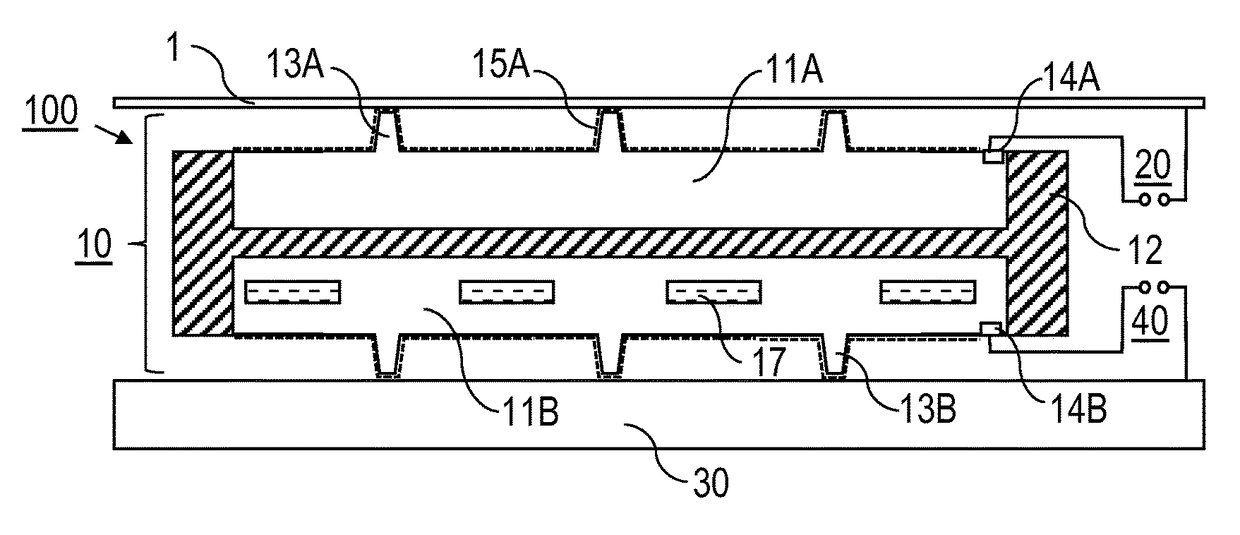
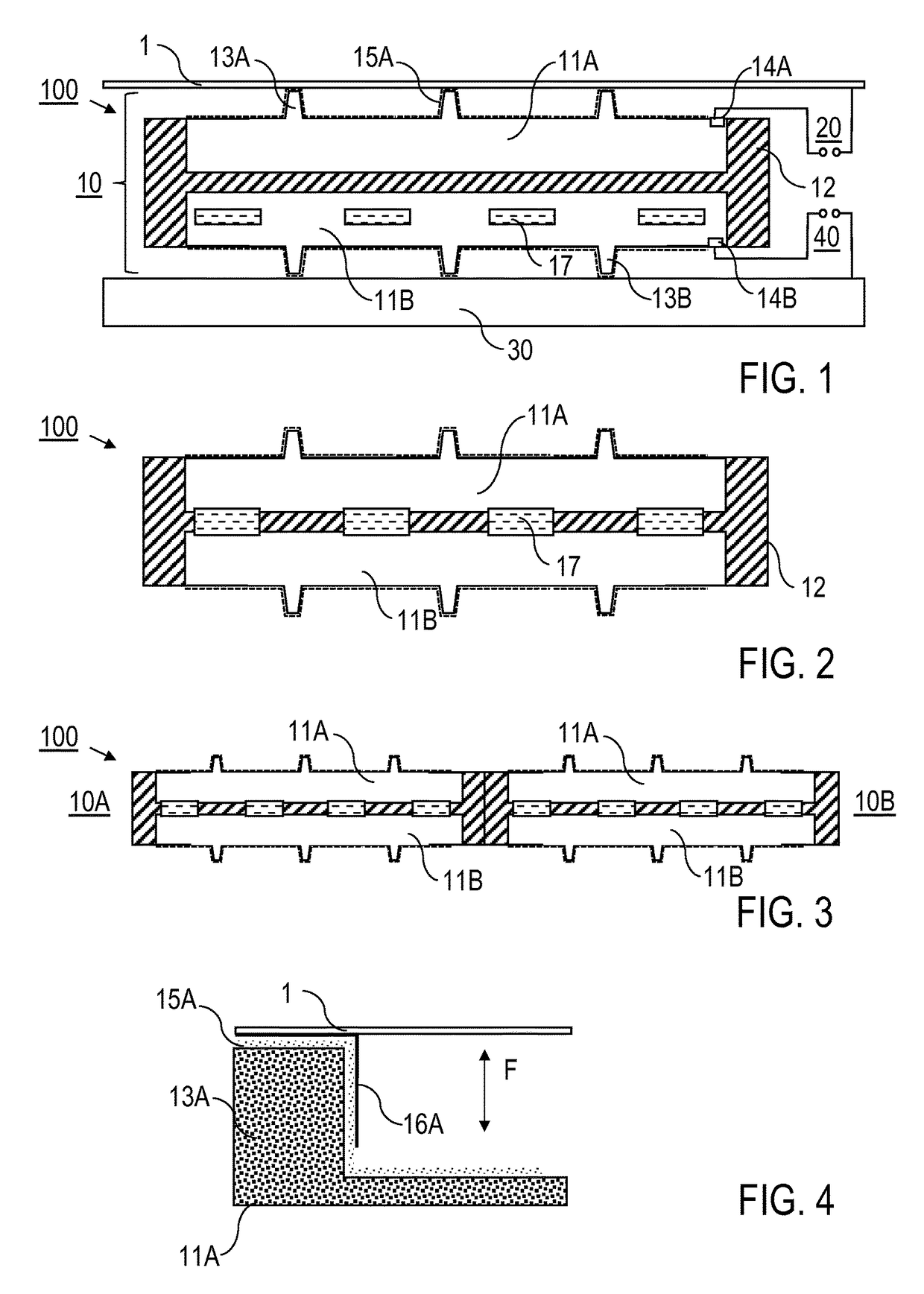
[0008]According to a first general aspect of the invention there is provided a holding apparatus for electrostatically holding a component, in particular a silicon wafer, having at least one base body which comprises at least one first plate and at least one second plate. The first plate is arranged on an upper side of the base body, on which a support surface for receiving the component is provided when the holding apparatus is in use. The second plate, which is made of an electrically insulating material, carries the first plate. The holding apparatus is equipped with a plurality of projecting, upper burls, which are also referred to as carrier elements, are arranged on the upper side of the base body and span a support surface for the component. The holding apparatus further has a first electrode (upper electrode) which is arranged to receive a clamping voltage. According to the invention, the first plate is produced from an electrically conductive, silicon-including (Si-based) c...


PUM

PropertyMeasurementUnit
thicknessaaaaaaaaaa
diameteraaaaaaaaaa
diameteraaaaaaaaaa

Abstract

A holding apparatus (100) for electrostatically holding a component (1), in particular a silicon wafer, includes at least one base body (10, 10A, 10B) which is composed of a first plate (11A) and a second plate (12), the first plate (11A) being arranged on an upper side (10A) of the base body (10, 10A, 10B) and the second plate are made of an electrically insulating material, a plurality of projecting, upper burls (13A) which are arranged on the upper side (10A) of the base body (10, 10A, 10B) and form a support surface for the component (1), and a first electrode which is arranged to receive a clamping voltage, wherein the first plate (11A) is made of an electrically conductive, silicon-including ceramic and forms the first electrode. A method for producing the holding apparatus (100) is also described.

Description

BACKGROUND OF THE INVENTION[0001]The invention relates to a holding apparatus being adapted to electrostatically hold a component, in particular a silicon wafer. The invention relates also to a method for producing the holding apparatus. Applications of the invention are in the provision of devices or tools for holding components by means of electrostatic forces, in particular for holding semiconductor components, for example silicon wafers.[0002]Holding apparatuses for holding components electrostatically, which are also referred to as electrostatic holding apparatuses, electrostatic clamping apparatuses, electrostatic clamps, ESCs or electrostatic chucks, are known in general. An important application of electrostatic holding apparatuses is in holding silicon wafers in lithographic semiconductor processing, for example in chip production, in which the particular advantages of electrostatic holding, such as the ease of switching of electrostatic holding or clamping forces, a high p...

Claims


Application Information

Patent Timeline
Patent Type & Authority Patents(United States)
IPC IPC(8): H02N13/00H01L21/683B23K35/30B23K35/22B23K35/24B23K35/32B23K1/00B23K35/02B23K35/00B23K35/40H01L21/687B23K1/19B23K101/20B23K101/40
CPCH02N13/00B23K1/00B23K1/0008B23K1/19B23K35/00B23K35/0205B23K35/0222B23K35/0238B23K35/222B23K35/24B23K35/30B23K35/302B23K35/3006B23K35/325B23K35/402H01L21/6831H01L21/6833H01L21/6875B23K2201/20B23K2201/40B23K2101/20B23K2101/40
Inventor BALDUS, OLIVER
Owner ASML NETHERLANDS BV
Why Eureka
Try Eureka