High frequency filter
a filter and high frequency technology, applied in the field of high frequency filters, can solve the problems of difficult to reduce the profile height of multi-layer balanced filters, and achieve the effect of preventing an increase in the mounting area and lowering the profile heigh
- Summary
- Abstract
- Description
- Claims
- Application Information
AI Technical Summary
Benefits of technology
Problems solved by technology
Method used
Image


Examples
first preferred embodiment
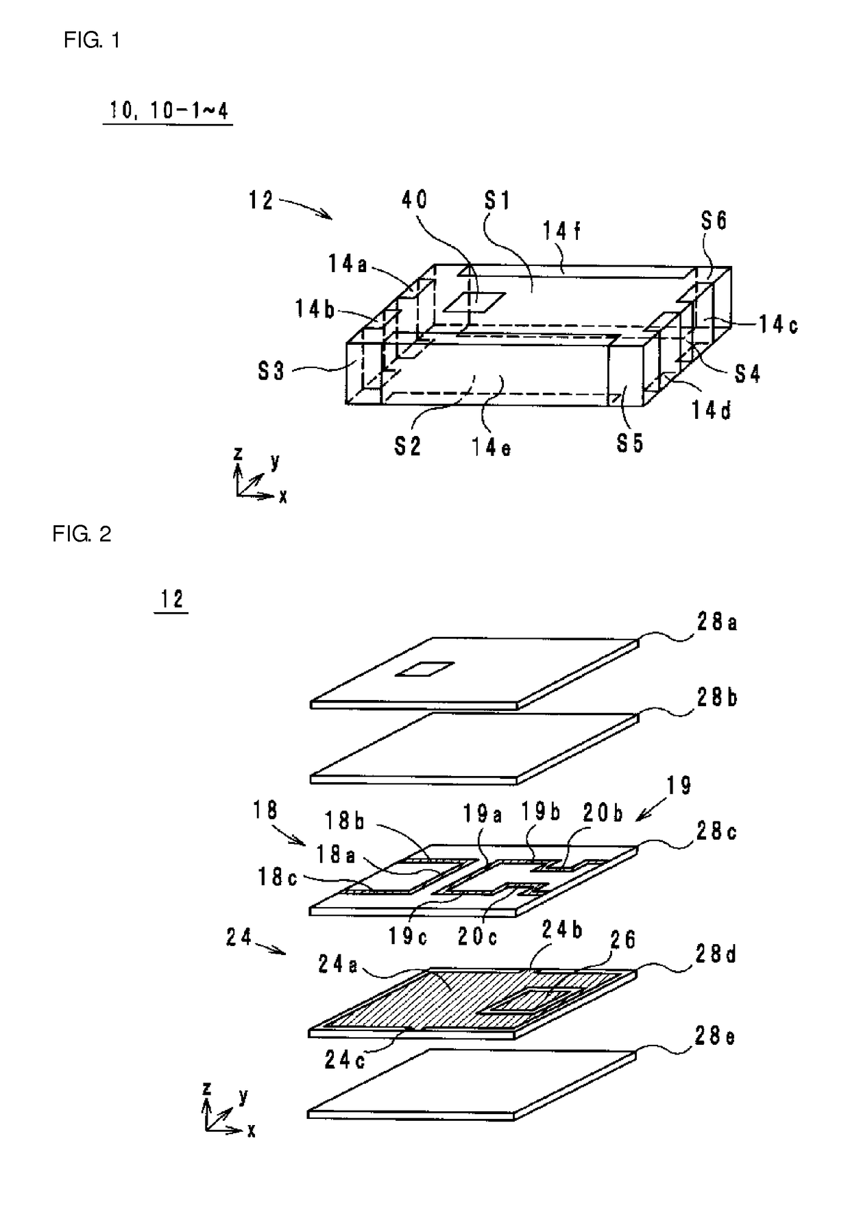
[0030]A high frequency filter according to the first preferred embodiment of the present invention is now described below with reference to the drawings. FIG. 1 is an external perspective view of the high frequency filter according to the first preferred embodiment. FIG. 2 is an exploded perspective view of a multilayer structure of the high frequency filter according to the first preferred embodiment. FIG. 3 is an equivalent circuit diagram of the high frequency filter according to the first preferred embodiment. Hereinafter, it is defined that a stacking direction of a high frequency filter 10 is a z-axis direction. Further, it is defined that, in a planar view in the z-axis direction, a direction along a longer side of the high frequency filter 10 is an x-axis direction, and a direction along a shorter side of the high frequency filter 10 is a y-axis direction. The x-axis, the y-axis, and the z-axis are perpendicular or substantially perpendicular to each other.
[0031]The high fre...
first modification example
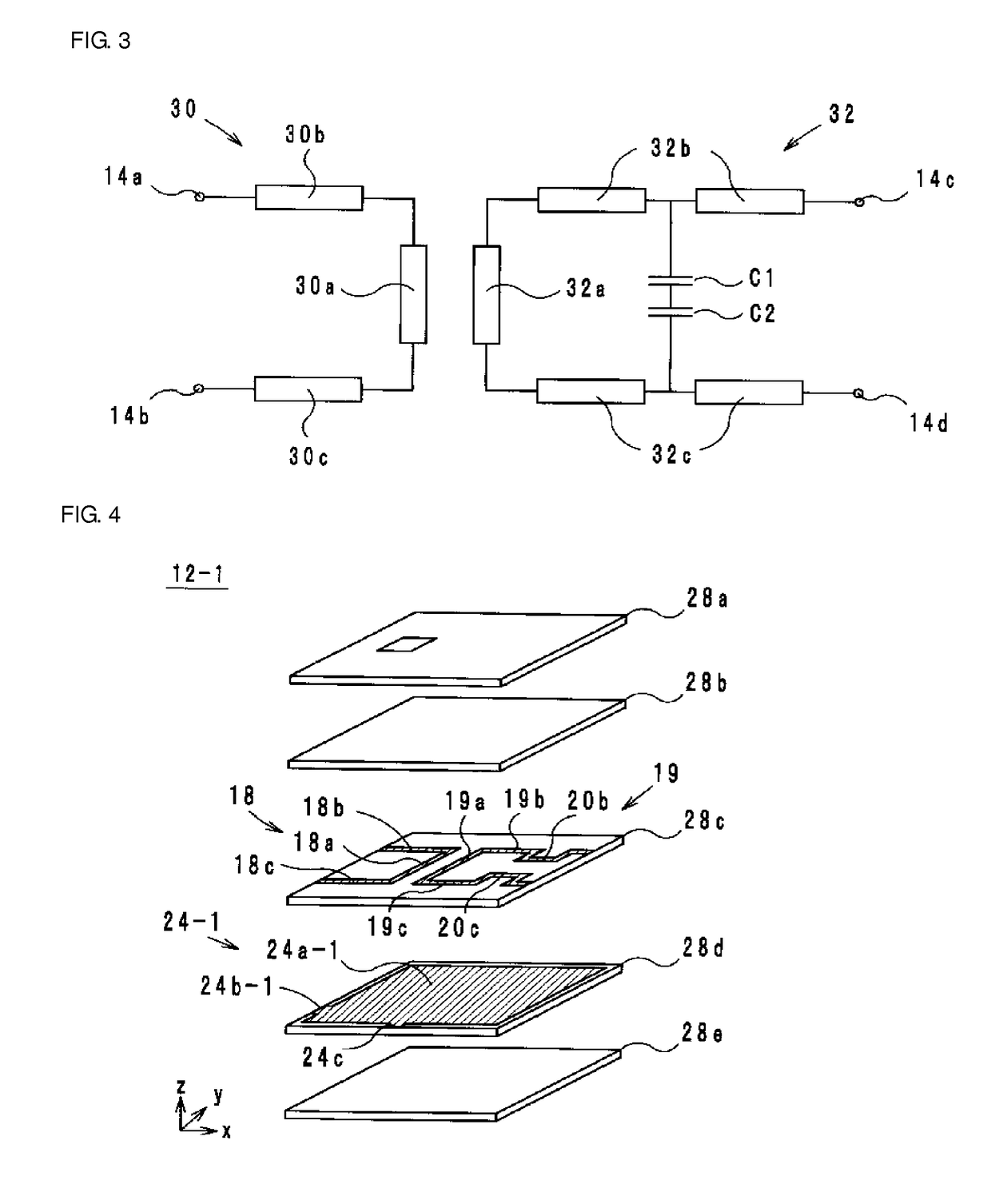
[0070]A high frequency filter 10-1 according to a first modification example of a preferred embodiment of the present invention is described below with reference to drawings. FIG. 4 is an exploded perspective view of a multilayer structure 12-1 of the high frequency filter 101 according to the first modification example. FIG. 5 is an equivalent circuit diagram of the high frequency filter 10-1 according to the first modification example illustrated in FIG. 4. As for the external perspective view, FIG. 1 is incorporated herein.
[0071]Differences between the high frequency filter 10 and the high frequency filter 10-1 lie in the shape of the ground conductor 24 and the presence or absence of the floating conductor 26. The remaining features are preferably identical or substantially identical in the high frequency filter 10 and the high frequency filter 10-1, and thus the descriptions thereof are omitted. Here, a ground conductor in the high frequency filter 10-1 is referred to as a grou...
second modification example
[0075]A high frequency filter 10-2 according to a second modification example of a preferred embodiment of the present invention is described below with reference to drawings. FIG. 6 is an exploded perspective view of a multilayer structure 12-2 of the high frequency filter 10-2 according to the second modification example. FIG. 7 is an equivalent circuit diagram of the high frequency filter 10-2 according to the second modification example illustrated in FIG. 6. As for the external perspective view, FIG. 1 is incorporated herein.
[0076]Differences between the high frequency filter 10 and the high frequency filter 10-2 lie in the shape of the ground conductor 24 and the presence or absence of the floating conductor 26. The remaining features are preferably identical or substantially identical in the high frequency filter 10 and the high frequency filter 10-2, and thus the descriptions thereof are omitted. Here, a ground conductor in the high frequency filter 10-2 is referred to as a ...
PUM
 Abstract
Description
Claims
Application Information
 - R&D
- Intellectual Property
- Life Sciences
- Materials
- Tech Scout
- Unparalleled Data Quality
- Higher Quality Content
- 60% Fewer Hallucinations
Browse by: Latest US Patents, China's latest patents, Technical Efficacy Thesaurus, Application Domain, Technology Topic, Popular Technical Reports.
© 2025 PatSnap. All rights reserved.Legal|Privacy policy|Modern Slavery Act Transparency Statement|Sitemap|About US| Contact US: help@patsnap.com