
Measuring device for measuring cerebral parameters

a measuring device and cerebral parameter technology, applied in the field of measuring devices, can solve the problems of inability to capture light from a sensor and reflected or scattered by the tissue, inability to localize the measured tissue region, and inability to interfere with or distorted measurement signals, so as to minimize the damage to the tissue from the insertion of the prob

Active Publication Date: 2017-06-06
NEMODEVICES
View PDF39 Cites 0 Cited by
  • Summary
  • Abstract
  • Description
  • Claims
  • Application Information

AI Technical Summary

Benefits of technology

The solution enables precise and reliable measurement of cerebral parameters with reduced tissue stress and interference, allowing for accurate localization and evaluation of subregions around the probe, enhancing the measurement of blood flow, hemoglobin values, and other markers.

Problems solved by technology

The measurement signal can thereby be interfered with or distorted.
Furthermore localization of the measured tissue region is difficult in the case of a measurement on the side of the probe.
The spacing of the sensors must be large to such an extent that light which is emitted from a sensor and is reflected or scattered by the tissue is not able to be captured by another sensor.
Furthermore some relevant parameters, such as oxygen content, cannot be determined with such a measuring probe.

Method used


Image

  • Measuring device for measuring cerebral parameters
  • Measuring device for measuring cerebral parameters

Examples


Embodiment Construction

[0030]Various embodiments of the present invention will now be described more fully hereinafter with reference to the accompanying drawings, in which some, but not all embodiments of the invention are shown. Indeed, embodiments of the invention may be embodied in many different forms and should not be construed as limited to the embodiments set forth herein. Rather, these embodiments are provided so that this disclosure will satisfy applicable legal requirements. Unless otherwise defined, all technical and scientific terms used herein have the same meaning as commonly known and understood by one of ordinary skill in the art to which the invention relates. The term “or” is used herein in both the alternative and conjunctive sense, unless otherwise indicated. Like numbers refer to like elements throughout.

[0031]Understood by a distal direction in the following is any direction in which an end of a measuring device points that is being inserted into a body tissue. This end is thus the ...


PUM


Abstract

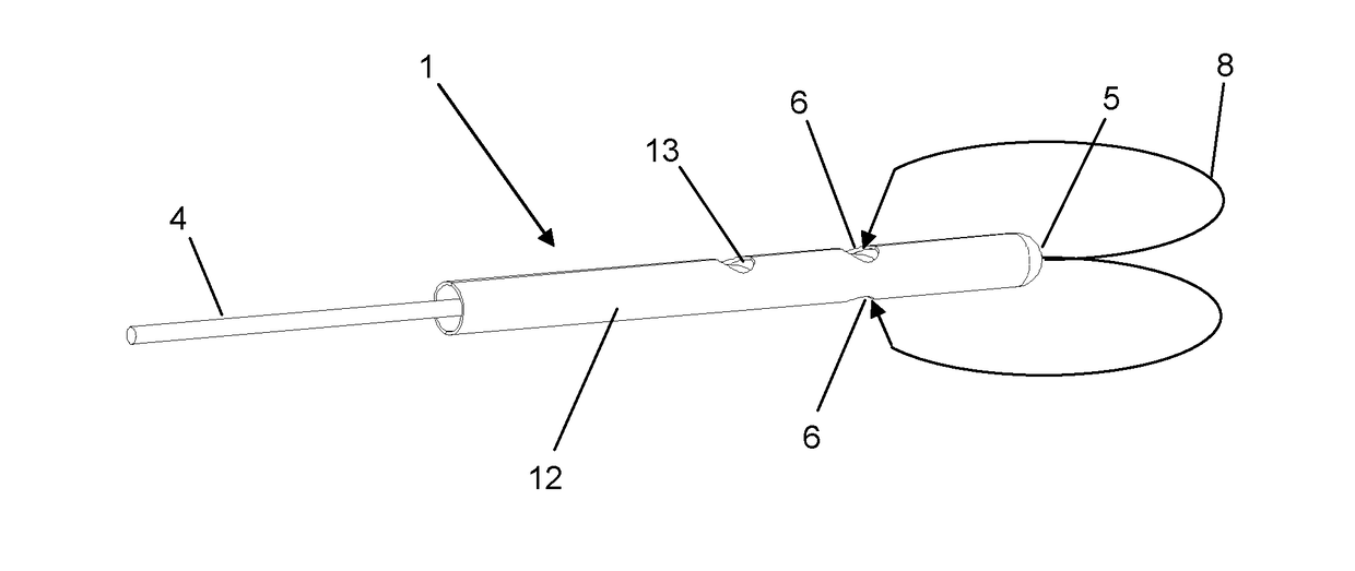
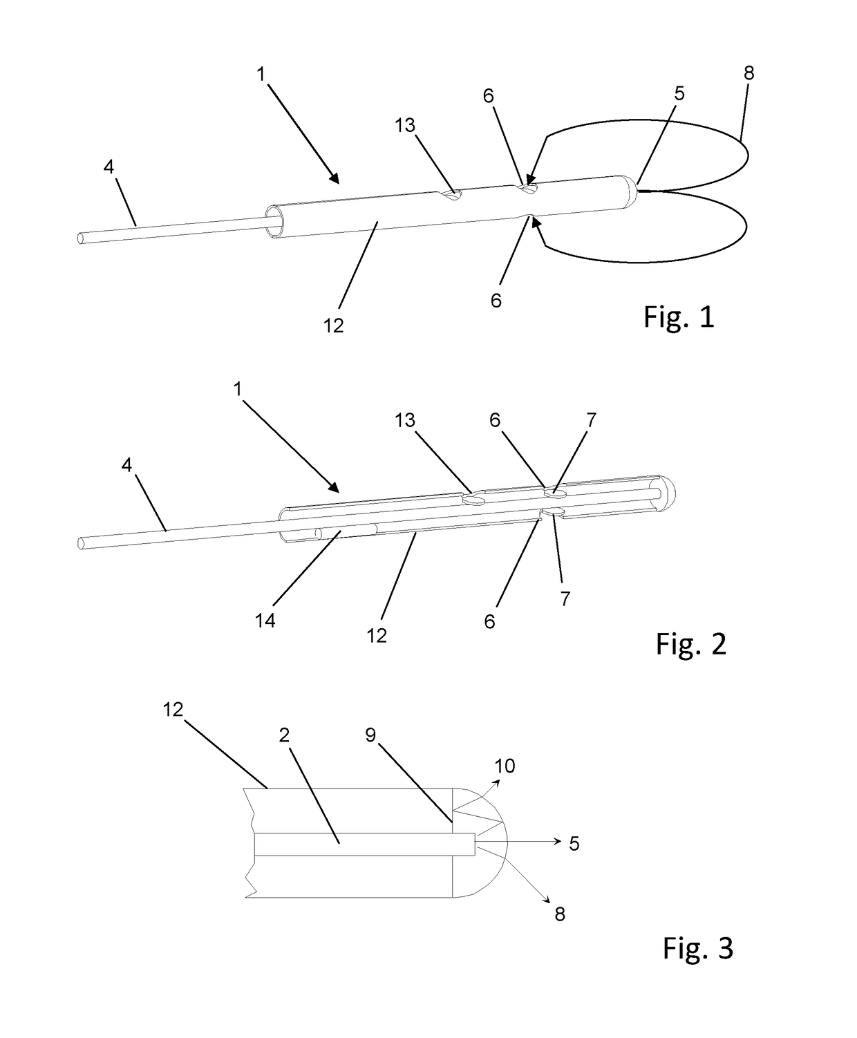
The invention relates to a measuring device and to a method for measuring parameters of a body tissue using an elongate probe (1) for insertion into the body tissue, comprising at least one optical waveguide (2) for transmitting light beams that runs along the longitudinal axis of the probe within the probe, an exit region (5) from which light beams emitted from the optical waveguide exit into the body tissue, and at least one receiving region (6) through which light beams reflected and / or scattered in the body tissue enter the probe as input light beams on a photodetector or in an optical waveguide (2; 3). The exit region (5) is provided at the distal end of the probe (1) and is oriented at least partially in the longitudinal direction of the probe (1). At least some of the emitted light beams exit the probe in the longitudinal direction of the probe. The at least one receiving region (6) is located at a distance from the distal end of the probe on a lateral circumferential region of the probe. The input light beams entering a receiving region (6) are subject to a deflection of more than 90° relative to the light beams emitted from the exit region (5).

Description

CROSS REFERENCE TO RELATED APPLICATIONS[0001]This application is a national stage application, filed under 35 U.S.C. §371, of International Application No. PCT / EP2012 / 052778, filed Feb. 17, 2012, which claims priority to Swiss Application No. 0774 / 11, filed May 5, 2011, the contents of both of which are hereby incorporated by reference in their entirety.BACKGROUND[0002]Related Field[0003]The invention relates to a measuring device and a method for measuring parameters of a body tissue using an elongated probe for insertion into the body tissue as set forth in the preamble of claim 1, in particular a measuring device for measuring cerebral parameters by means of an invasive measuring procedure.[0004]Description of Related Art[0005]Various invasive procedures for cerebral diagnostics and therapy are known in which different cerebral parameters are measured, such as cerebral hemodynamics. Measured are, for example, parameters relating to the concentration of deoxygenated and oxygenated...

Claims


Application Information

Patent Timeline
Patent Type & Authority Patents(United States)
IPC IPC(8): A61B5/00A61B5/1455A61B5/1459
CPCA61B5/14553A61B5/0084A61B5/1459A61B5/14552
Inventor FROHLICH, JURG HANSMUSER, MARKUS HUGO
Owner NEMODEVICES
Learn More