
Blind source separation systems

a source separation and source separation technology, applied in the field of blind source separation systems, can solve the problems of severe curtailment of people's ability to interact in normal social situations, difficulty in adjusting the position of the source, and difficulty in adjusting the position, so as to reduce the dimensionality of data, reduce the cost of rotation, and avoid the effect of being trapped in local maxima

Active Publication Date: 2017-05-30
AUDIOTELLIGENCE LTD
View PDF12 Cites 67 Cited by
  • Summary
  • Abstract
  • Description
  • Claims
  • Application Information

AI Technical Summary

Benefits of technology

The patent describes a method and apparatus for improving audibility of audio signals by blind source separation. The method involves digitizing signals from microphones, converting them to the time-frequency domain, and using a blind source separation module to determine a demixing matrix for the audio sources. The apparatus filters the signals in the time domain based on the demixing matrix to select the audio sources. The technical effects of the invention include improved audibility of audio signals through effective source separation and improved overall quality of the audio signals.

Problems solved by technology

This is especially true of the over 50s, and it is one of the first signs of age-related hearing loss, which severely curtails people's ability to interact in normal social situations.
This can lead to a sense of isolation that has a profound influence on general lifestyle, and many studies suggest that it may contribute to dementia.
Consequently, many sufferers may be unaware that they have a hearing problem and conventional hearing aids are not very effective.
However this approach can suffer from problems if power at one frequency may be correlated with the absence of power at another frequency, for example the voiced and unvoiced parts of speech.
However whilst this can distinguish between characteristically different voices, such as male and female speakers, it has difficulty with finer distinctions.
In addition this approach can introduce substantial latency into the processed signal, making it unsuitable for real time use and thus unsuitable, for example, to assist in listening to a conversation.

Method used


Image

  • Blind source separation systems
  • Blind source separation systems
  • Blind source separation systems

Examples


example implementations

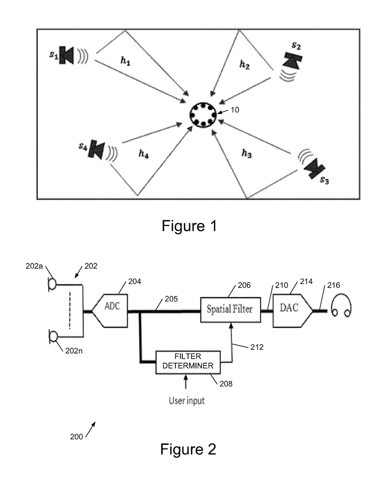
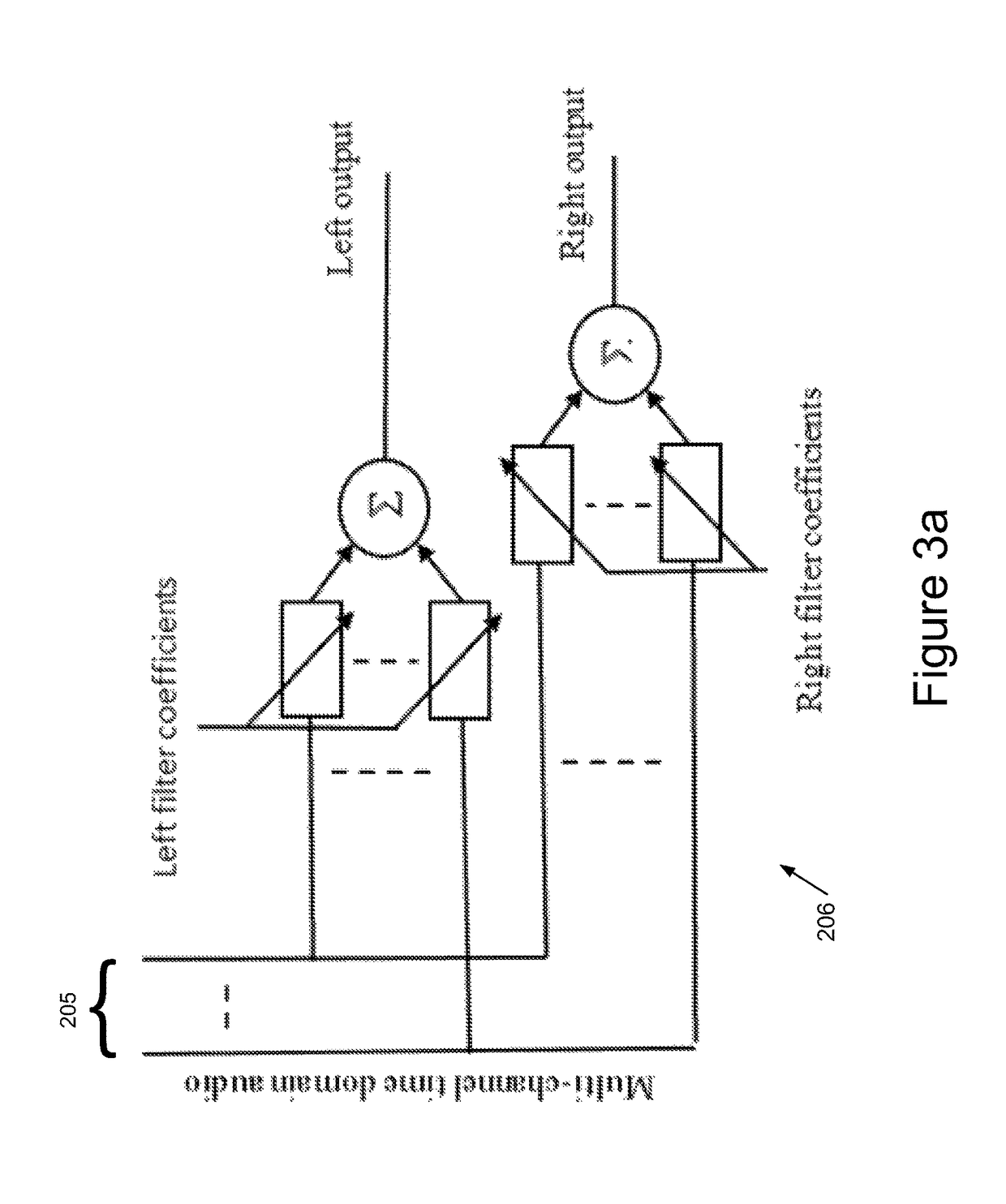
[0201]Referring to FIG. 2, this shows the architecture of apparatus 200 to improve the audibility of an audio signal by blind source separation, employing time-domain filtering to provide low latency. The apparatus comprises a microphone array 202 with microphones 202a-n, coupled to a multi-channel analogue-to-digital converter 204. This provides a digitised multi-channel audio output 205 to a spatial filter 206 which may be implemented as a multi-channel linear convolutional filter, and to a filter coefficient determiner 208. The filter coefficient determiner 208 determines coefficients of a demixing filter which are applied by spatial filter 206 to extract audio from one (or more) selected sources for a demixed audio output 210. The filter determiner 208 accepts optional user input, for example to select a source, and has an output 212 comprising demixing filter coefficients for the selected source. The demixed audio 210 is provided to a digital-to-analogue converter 214 which pro...


PUM


Abstract

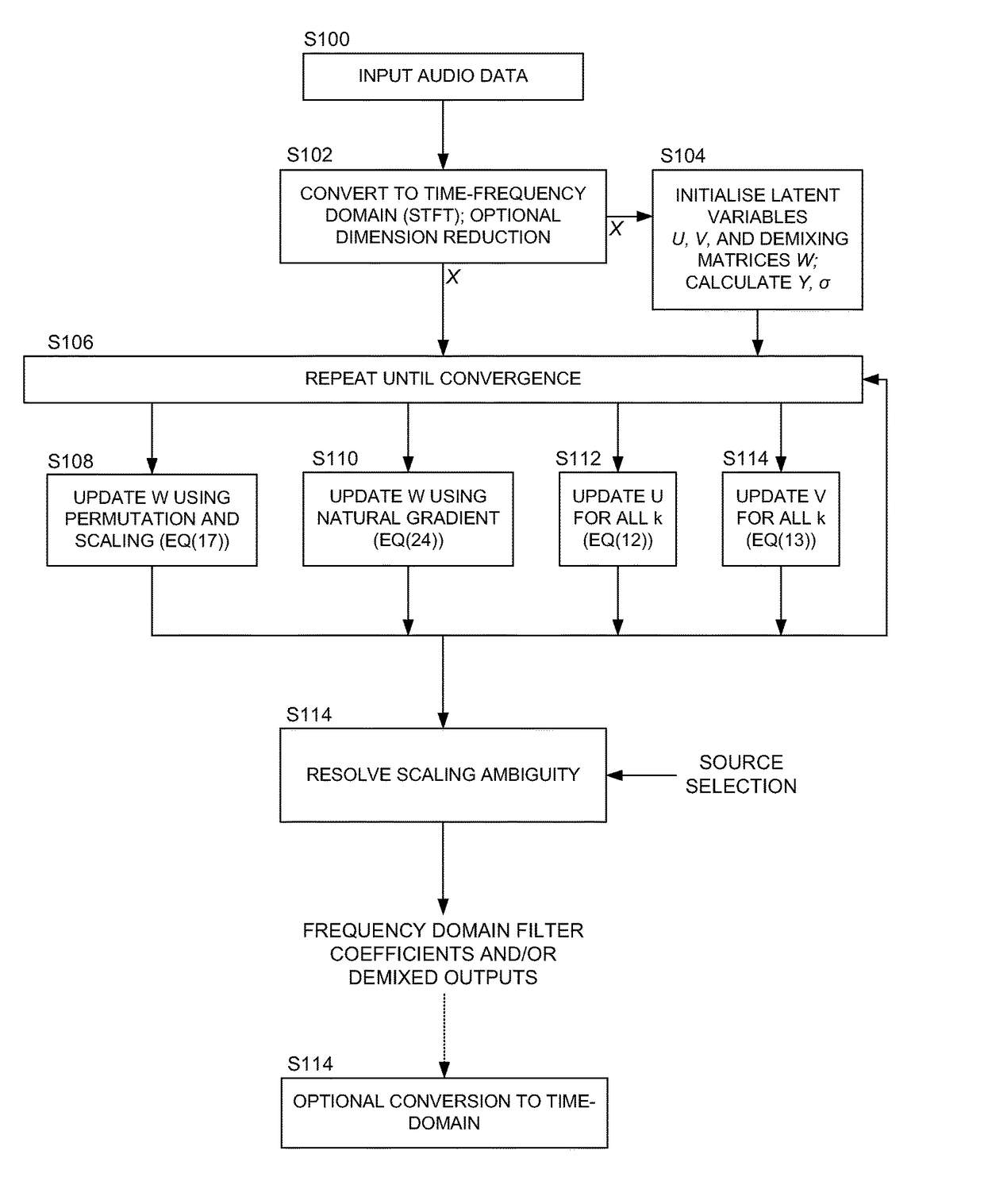
We describe a method of blind source separation for use, for example, in a listening or hearing aid. The method processes input data from multiple microphones each receiving a mixed signal from multiple audio sources, performing independent component analysis (ICA) on the data in the time-frequency domain based on an estimation of a spectrogram of each acoustic source. The spectrograms of the sources are determined from non-negative matrix factorization (NMF) models of each source, the NMF model representing time-frequency variations in the output of an acoustic source in the time-frequency domain. The NMF and ICA models are jointly optimized, thus automatically resolving an inter-frequency permutation ambiguity.

Description

RELATED APPLICATIONS[0001]This application is a continuation of U.S. patent application Ser. No. 14 / 678,419, filed 3 Apr. 2015, which is incorporated herein in its entirety.FIELD OF THE INVENTION[0002]This invention relates to methods, apparatus and computer program code for blind source separation, for example to assist listeners with hearing loss in distinguishing between multiple different simultaneous speakers.BACKGROUND TO THE INVENTION[0003]Many people's ability to understand speech is dramatically reduced in noisy environments such as restaurants and meeting rooms. This is especially true of the over 50s, and it is one of the first signs of age-related hearing loss, which severely curtails people's ability to interact in normal social situations. This can lead to a sense of isolation that has a profound influence on general lifestyle, and many studies suggest that it may contribute to dementia.[0004]With this type of hearing loss, listeners do not necessarily suffer any degra...

Claims


Application Information

Patent Timeline
IPC IPC(8): G10L21/02H04R25/00G10L21/0272G10L21/0216
CPCH04R25/40H04R2225/43H04R2430/20G10L21/0272G10L21/02G10L2021/02166H04R25/554H04R3/005H04R25/405H04R1/406
Inventor BETTS, DAVID ANTHONYDMOUR, MOHAMMAD A.
Owner AUDIOTELLIGENCE LTD
Learn More