
Removing faults from a self-healing film capacitor

a self-healing film and capacitor technology, applied in the direction of capacitors, fixed capacitor details, capacitor housing/encapsulation, etc., can solve the problems of affecting the operation, affecting the operation, and affecting the operation, so as to achieve the effect of high pressure-increasing rate and short time constan

Active Publication Date: 2017-05-30
SIEMENS ENERGY AS
View PDF15 Cites 2 Cited by
  • Summary
  • Abstract
  • Description
  • Claims
  • Application Information

AI Technical Summary

Benefits of technology

The patent describes a method for producing a capacitor that can operate in a pressurized environment, such as a subsea location close to the ocean floor. The method involves applying a voltage to the capacitor to initiate a healing process that can remove faults or defects, which can cause small short-circuits between the layers of the capacitor. This healing process can reduce the number of faults or defects, ensuring the capacitor operates properly in the pressurized environment. The treated capacitor can be installed in a pressurized enclosure to avoid malfunction when operated in high-pressure environments.

Problems solved by technology

Therefore, components to be used in subsea applications may have to withstand and operate properly at this pressure.
Film capacitors may include faults that hamper the operation thereof.
After the above-described process stages, the manufactured capacitors may have produced defects in the dielectric film or metallization (e.g., defects, weaknesses, pinholes and flaws).
In addition, foreign or undesired particles may be trapped between film layers, or there may be production inaccuracies in the dielectric film or metallization layer.
Conventional healing processes for healing a capacitor (e.g., a self-healing film capacitor) may not be of sufficient accuracy or reliability for all conditions, such as for preparing capacitors for subsea applications.

Method used


Image

  • Removing faults from a self-healing film capacitor
  • Removing faults from a self-healing film capacitor

Examples


Embodiment Construction

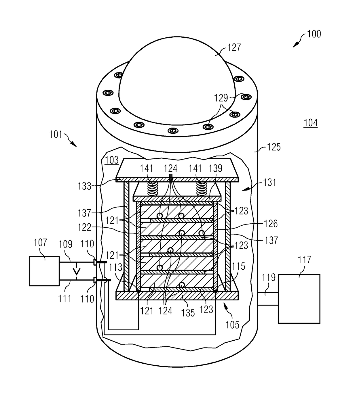
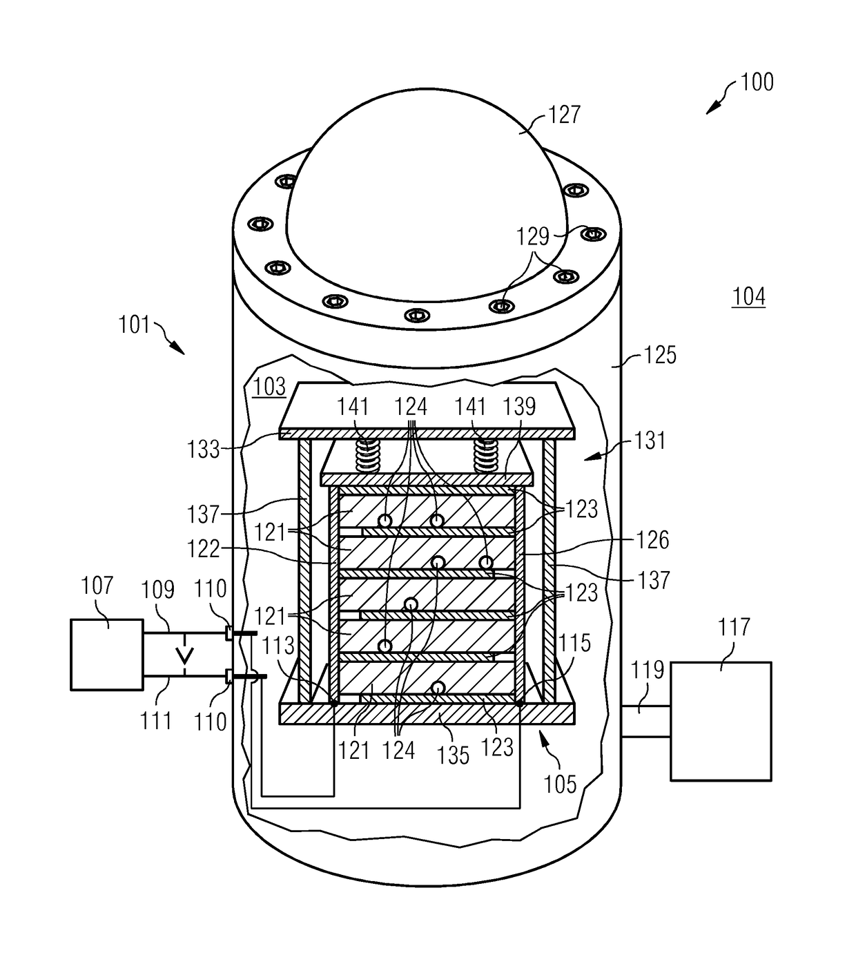
[0052]The apparatus 100 in FIG. 1 includes a vessel 101 containing a non-conductive fluid 103. The non-conductive fluid 103 surrounds a capacitor 105 that, in the example shown in FIG. 1, is a self-healing film capacitor. The apparatus 100 further includes a voltage source 107 that is configured to generate a voltage V between first terminal 109 and second terminal 111, and to apply the voltage (e.g., via connectors 110) to a first electrode 113 and a second electrode 115 of the capacitor 105, thereby charging the capacitor 105. The apparatus 100 further includes a pressurizing system 117 that is connected via a port 119 to the interior of the vessel 101 in order to pressurize the non-conductive fluid 103 in the vessel 101 from a start pressure p1 (e.g., when the interior of the vessel 101 is in communication with the air pressure104 outside the vessel) to a target pressure p2. The capacitor 105 includes stacked dielectric layers 121 having metal layers 123 deposited thereon. The me...


PUM


Abstract

A method for treating a capacitor for healing faults therein includes: applying a voltage between a first electrode and a second electrode of the capacitor to charge the capacitor at a start pressure; and pressurizing a non-conductive fluid surrounding the capacitor to a target pressure while the voltage is applied.

Description

RELATED APPLICATIONS[0001]This application claims the benefit of European Patent Application No. EP 13197486.7, filed Dec. 16, 2013. The entire contents of the priority document are hereby incorporated herein by reference.TECHNICAL FIELD[0002]The present teachings relate generally to methods and apparatuses for treating a capacitor (e.g., a self-healing film capacitor) for healing faults. In some embodiments, the capacitor is used in subsea applications.BACKGROUND[0003]A power grid may be operated at a sea ground or subsea. A power grid may include an adjustable speed drive (ASD) with one or more power cells that may have a DC-link capacitor as a component. Each power cell may contain a large DC-link capacitor. In a subsea application, smaller capacitors may be used for power supply and circuit boards. In a subsea application or subsea power grid, components (including the power cell in the subsea ASD) may be located in a pressure-compensated oil volume (e.g., contained within a ves...

Claims


Application Information

Patent Timeline
Patent Type & Authority Patents(United States)
IPC IPC(8): H01G4/015H01G4/224H01G2/10
CPCH01G4/015H01G2/10H01G4/224
Inventor AARSKOG, FREDRIK GUNDERSEN
Owner SIEMENS ENERGY AS
Learn More