
Bearing unit of turbo-charger

a technology of bearing unit and turbocharger, which is applied in the direction of sliding contact bearings, mechanical equipment, machines/engines, etc., can solve the problems of long rotary shaft and long entire length of turbochargers, and achieve the effect of preventing lubricant from leaking

Active Publication Date: 2017-05-23
HYUNDAI MOTOR CO LTD
View PDF10 Cites 0 Cited by
  • Summary
  • Abstract
  • Description
  • Claims
  • Application Information

AI Technical Summary

Benefits of technology

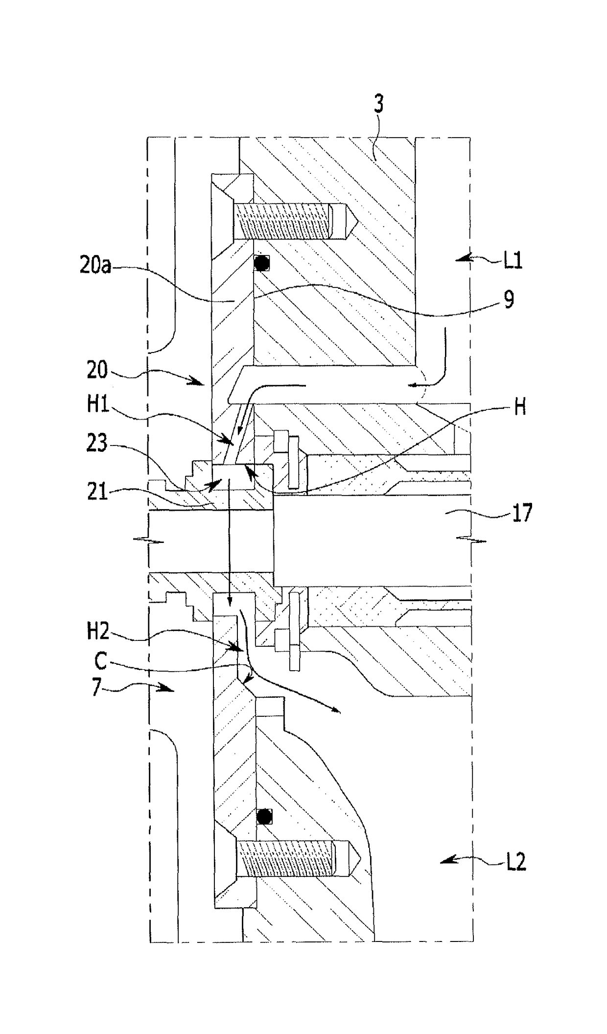
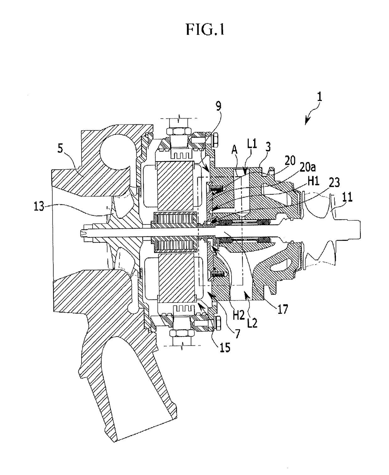
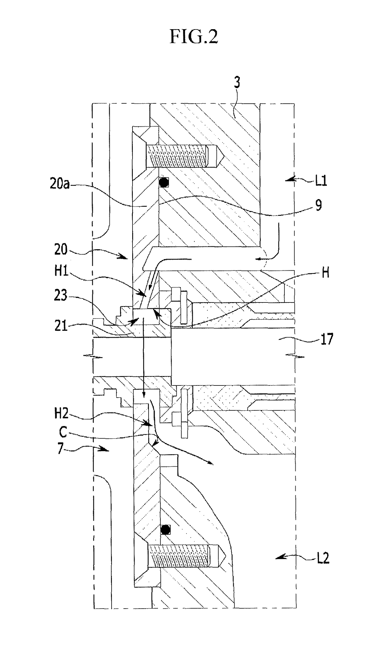
The present invention provides a bearing unit for a turbocharger that can carry the axial load of a rotary shaft and prevent lubricant from leaking to the electric motor. It also reduces the length of the rotary shaft, thus reducing the overall size of the turbocharger.

Problems solved by technology

However, since the sealing bracket, the thrust bearing, and the oil deflector are disposed in a line on the rotary shaft, the rotary shaft needs to be long, and accordingly, the entire length of the turbochargers is long.

Method used


Image

  • Bearing unit of turbo-charger
  • Bearing unit of turbo-charger
  • Bearing unit of turbo-charger

Examples


Embodiment Construction

[0020]Reference will now be made in detail to various embodiments of the present invention(s), examples of which are illustrated in the accompanying drawings and described below. While the invention(s) will be described in conjunction with exemplary embodiments, it will be understood that the present description is not intended to limit the invention(s) to those exemplary embodiments. On the contrary, the invention(s) is / are intended to cover not only the exemplary embodiments, but also various alternatives, modifications, equivalents and other embodiments, which may be included within the spirit and scope of the invention as defined by the appended claims.

[0021]The sizes and thicknesses of the configurations shown in the drawings are provided selectively for the convenience of description, such that the present invention is not limited to those shown in the drawings and the thicknesses are exaggerated to make some parts and regions clear. Further, parts that are not related to the ...


PUM


Abstract

A bearing unit of a turbocharger may be disposed on an inner side of a space in a center housing and carry axial load of a rotary shaft connecting a turbine wheel, a compressor wheel, and an electric motor. The bearing unit may include a bearing body fastened to a side of the center housing and has a through-hole substantially at a center of the bearing body, and a coupling disposed in the through-hole and on the rotary shaft, having a stepped portion in which the bearing body is inserted, and forming an oil chamber with the bearing body.

Description

CROSS-REFERENCE TO RELATED APPLICATION[0001]The present application claims priority of Korean Patent Application Number 10-2012-0158628 filed Dec. 31, 2012, the entire contents of which application are incorporated herein for all purposes by this reference.BACKGROUND OF INVENTION[0002]Field of Invention[0003]The present invention relates to a bearing unit of a turbocharger. More particularly, the present invention relates to a bearing unit of a turbocharger which prevents a lubricant from leaking to an electric motor while carrying axial load of a rotary shaft in a center housing of an electric turbocharger.[0004]Description of Related Art[0005]In general, a turbocharger is a device that turns a turbine using exhaust gas from an engine and then increases the output of the engine by supplying high-pressure air into a combustion chamber, by operating the compressor using the torque of the turbine.[0006]Electric turbochargers, which can operate a rotary shaft of the turbochargers with ...

Claims


Application Information

Patent Timeline
Patent Type & Authority Patents(United States)
IPC IPC(8): F01D25/16F16C33/10F01D25/18F16C17/04
CPCF01D25/18F16C33/1025F01D25/168F05D2220/40F05D2240/52F05D2260/609F16C17/04F16C2360/24F01D25/16F02B39/10F02B39/14
Inventor YEOM, KITAEYANG, JAESIKKIM, SUNG WONHWANG, TAE WONLEE, HONG-YOUNG
Owner HYUNDAI MOTOR CO LTD
Learn More