Eureka AIR delivers breakthrough ideas for toughest innovation challenges, trusted by R&D personnel around the world.

System and method for monitoring and controlling an HVAC system

a technology applied in the field of systems and methods for monitoring and controlling hvac systems, can solve the problems of reducing the ability of the hvac system to circulate air, clogging filters, requiring more energy, etc., and achieve the effect of monitoring the efficiency and/or efficacy of the system

Active Publication Date: 2017-05-09
SYST PERFORMANCE TECH LLC
View PDF10 Cites 17 Cited by
  • Summary
  • Abstract
  • Description
  • Claims
  • Application Information

AI Technical Summary

Benefits of technology

The present invention introduces a system and method for monitoring and controlling an HVAC system. The system includes a control device that can assess the energy efficiency of the system and control its components accordingly. The control device also monitors the status of the filter and other components of the system, and can adjust their operations accordingly. This results in a more efficient and effective HVAC system.

Problems solved by technology

Clogged filters reduce the ability of the HVAC system to circulate air, reducing effectiveness and requiring more energy.
As it is generally difficult to determine the condition of a filter, most filter replacements are performed on a time basis, or a total-operating-hours basis.
This can lead to a loss of efficiency if the filter becomes clogged unusually quickly (for example, due to heavy pollution in the area), or a wasted filter replacement if the filter has not yet become significantly clogged.
While this reference teaches monitoring the system, it is not able to take any action itself in the event of the filter becoming clogged, it can only report that the filter requires replacement.
While this prior art system teaches the monitoring of the HVAC system, it does not enable active control over the system.

Method used


Image

  • System and method for monitoring and controlling an HVAC system
  • System and method for monitoring and controlling an HVAC system
  • System and method for monitoring and controlling an HVAC system

Examples


Embodiment Construction

[0030]The above-described drawing figures illustrate the invention, a system 10 for monitoring and controlling an HVAC system 100.

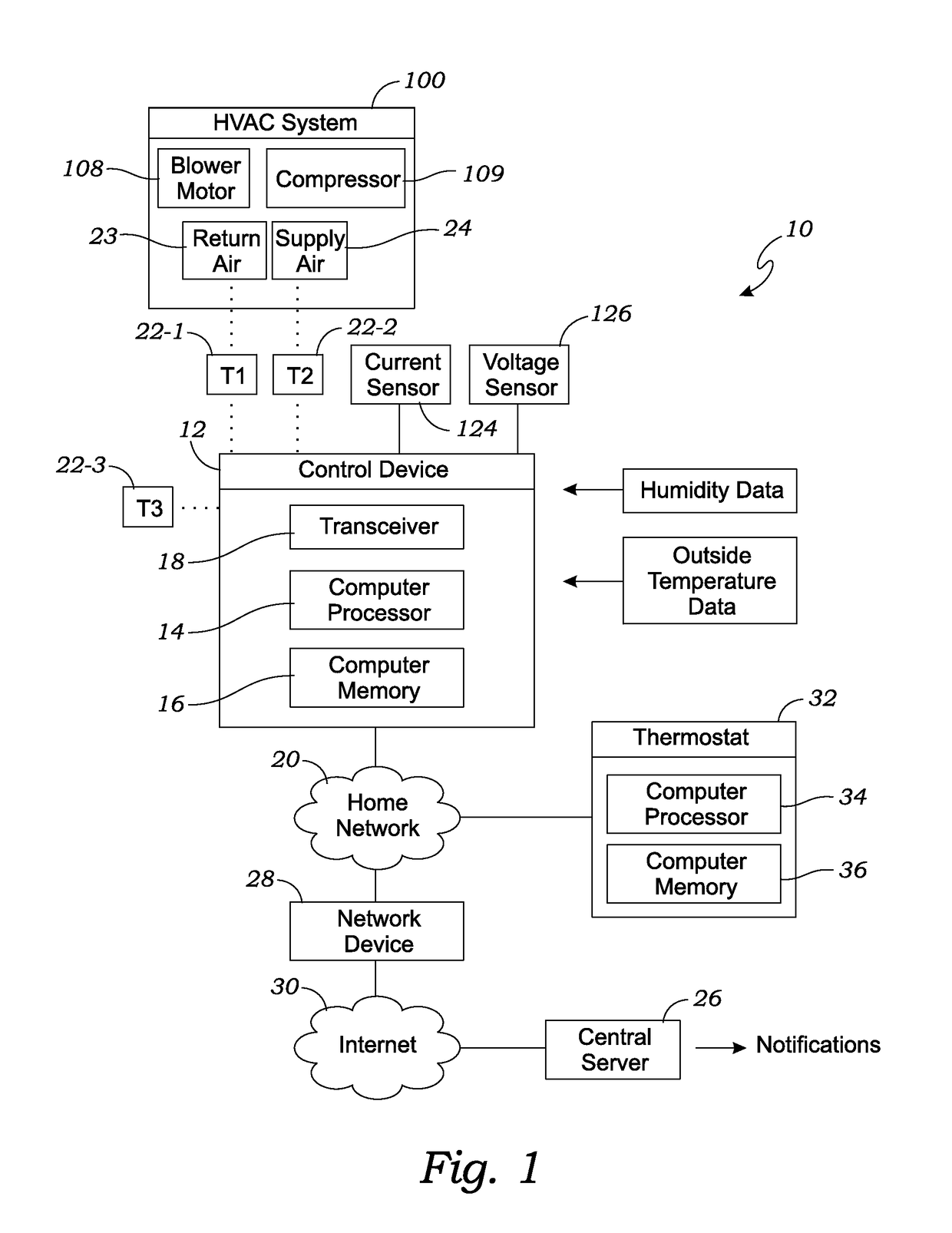
[0031]FIG. 1 is a block diagram of one embodiment of the system 10 for monitoring and controlling the HVAC system 100. The HVAC system 100 includes standard components, such as a blower motor 108 and a compressor 109, as well as any other powered components that may be required, or associated with the HVAC system 100. As shown in FIG. 1, the system 10 includes a control device 12 that includes a computer processor 14 and a computer memory 16 that includes the software for monitoring and controlling the HVAC system 100.

[0032]The control device 12 includes one or more computer devices that include executable code that, when executed, enables the system 10 to perform processes that are described in greater detail below. The processor 14 may include, for example, microprocessors, microcomputers, microcontrollers, digital signal processors, central processing ...


PUM


Abstract

A system and method for monitoring and controlling an energy demand by an HVAC system utilizes a control device that is operably installed in the HVAC system. The system performs the following steps: receiving, in a control device, values of one or more parameters related to performance of the plurality of powered components; comparing the received values with corresponding predetermined threshold values; determining overloading of the electrical grid by a powered component based on respective values of one or more parameters being less than the corresponding predetermined threshold values for the powered component; and selectively controlling the operation of the powered component without disrupting operation of the remaining plurality of powered components.

Description

CROSS-REFERENCE TO RELATED APPLICATIONS[0001]This application for a utility patent is a continuation-in-part of a previously filed utility patent, having the application Ser. No. 14 / 811,816, filed Jul. 28, 2015, which claims the benefit of U.S. Provisional Application No. 62 / 030,025, filed Jul. 28, 2014, the contents of which are incorporated by reference in full.BACKGROUND OF THE INVENTION[0002]Field of the Invention[0003]This invention relates to systems and methods for monitoring and controlling HVAC systems, and more particularly to a system which continuously monitors the HVAC system and determines if maintenance is required.[0004]Description of Related Art[0005]It is important to maintain heating, ventilating, and air conditioning (HVAC) systems in good working order to maintain optimum energy efficiency. Clogged filters reduce the ability of the HVAC system to circulate air, reducing effectiveness and requiring more energy. As it is generally difficult to determine the condit...

Claims


Application Information

Patent Timeline
Patent Type & Authority Patents(United States)
IPC IPC(8): G05B15/02F24F11/00
CPCF24F11/006G05B15/02Y04S20/244F24F2011/0093F24F2011/0075F24F2011/0046F24F2011/0047G05B2219/2642F24F11/30F24F2140/50F24F2140/60F24F11/62F24F11/46F24F11/39F24F11/49F24F11/64
Inventor FRANCIS, BRIAN MARKROSENTRETER, DONALD RAYMONDKEOWN, DAN LEE
Owner SYST PERFORMANCE TECH LLC
Why Eureka
Eureka Blog
Learn More