
Harmonics suppression circuit for a switch-mode power amplifier

a power amplifier and harmonic suppression technology, applied in the direction of amplifiers, amplifier types, amplifiers with semiconductor devices/discharge tubes, etc., can solve the problems of consuming a relatively large portion of the period in a high frequency signal, undesirable harmonics, and slow rise and fall times or edges of signals

Active Publication Date: 2017-05-02
HONG KONG APPLIED SCI & TECH RES INST
View PDF12 Cites 34 Cited by
  • Summary
  • Abstract
  • Description
  • Claims
  • Application Information

AI Technical Summary

Benefits of technology

The present invention relates to improving harmonics suppression in power amplifiers. The technical effect of this invention is to reduce harmonics in power amplifiers, which can cause problems in meeting regulatory requirements. The invention proposes various methods to suppress harmonics, including using a bias generation circuit and a reduced-harmonics power amplifier with a gated-on transistor. The invention also discusses the use of a harmonics-reducing bias generator and multiple power amplifier cells. Overall, the invention aims to provide a more effective solution for reducing harmonics in power amplifiers.

Problems solved by technology

Unfortunately, even and odd harmonics are often generated above the fundamental frequency.
These harmonics are undesirable as they can violate emission limits set by regulatory agencies such as the U.S. Federal Communications Commission (FCC).
Thus rise and fall times or edges of signals are slow and consume a relatively large portion of the period in a high frequency signal.
Rising and falling edges may mismatch significantly.
Distortions that are thought to create harmonic distortions may be caused by rising and falling edge mismatch, and duty-cycle mismatch when the rising and falling times cause the duty cycle to deviate from 50%.

Method used


Image

  • Harmonics suppression circuit for a switch-mode power amplifier
  • Harmonics suppression circuit for a switch-mode power amplifier
  • Harmonics suppression circuit for a switch-mode power amplifier

Examples


Embodiment Construction

[0016]The present invention relates to an improvement in harmonics suppression for power amplifiers. The following description is presented to enable one of ordinary skill in the art to make and use the invention as provided in the context of a particular application and its requirements. Various modifications to the preferred embodiment will be apparent to those with skill in the art, and the general principles defined herein may be applied to other embodiments. Therefore, the present invention is not intended to be limited to the particular embodiments shown and described, but is to be accorded the widest scope consistent with the principles and novel features herein disclosed.

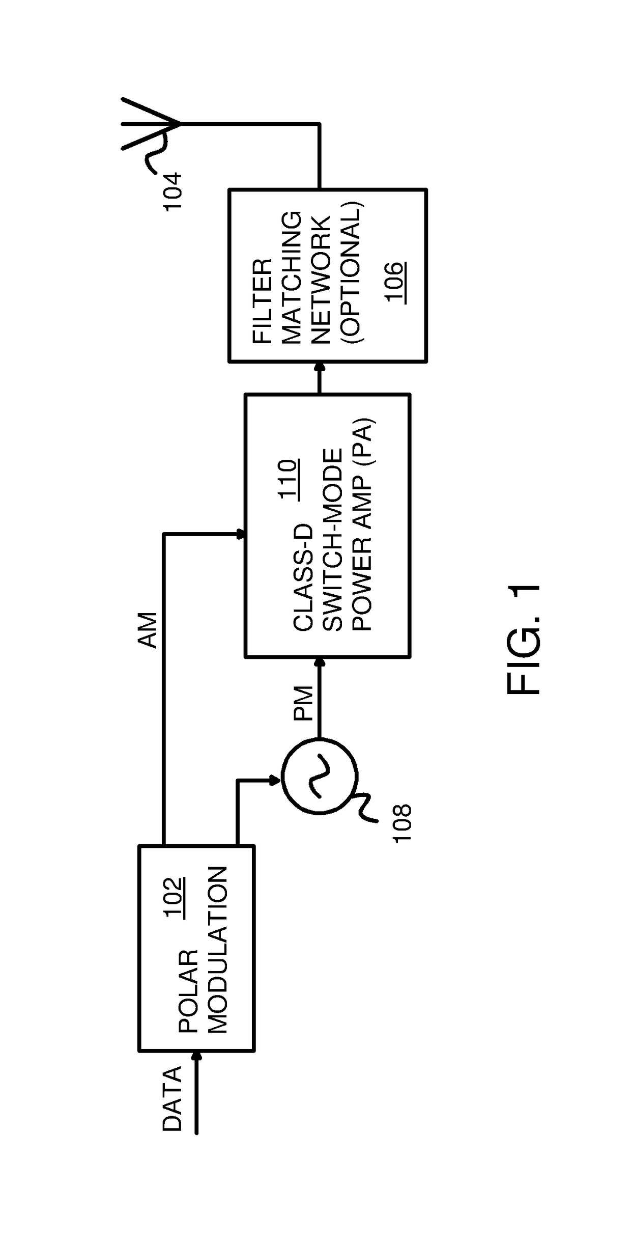
[0017]FIG. 1 is a block diagram of a Radio-Frequency (RF) polar transmitter. Data to be transmitted is modulated by polar modulator 102 to generate Amplitude-Modulation (AM) and Phase Modulation (PM) signals. The phase or frequency of local oscillator 108 is modulated under the control of polar modulator 102...


PUM


Abstract

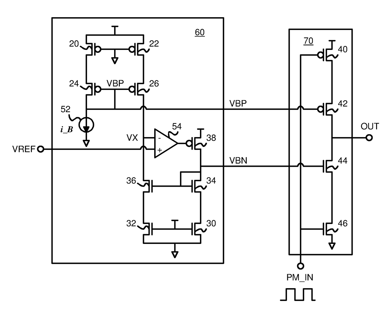
Even harmonics are suppressed by a harmonics-reducing bias generator that drives bias voltages to cascode control transistors in series with driver transistors in a power amplifier. A first bias voltage is generated by mirroring pull-up currents in the power amplifier. A p-channel source transistor and a p-channel cascode current-mirror transistor also mirror the power amplifier pull-up current to a midpoint node. An n-channel sink transistor and an n-channel cascode current-mirror transistor mirror the pull-down current in the power amplifier to the midpoint node. An op amp compares the midpoint node to VDD / 2, and drives the gate of a p-channel feedback transistor. Current from the p-channel feedback transistor flows through an n-channel cascode current-mirror transistor that generates a second bias voltage. The second bias voltage is adjusted until the midpoint node reaches VDD / 2, causing the pull-up and pull-down currents in the power amplifier to better match, reducing even harmonics.

Description

FIELD OF THE INVENTION[0001]This invention relates to power amplifier circuits, and more particularly to suppression of harmonics in power amplifiers.BACKGROUND OF THE INVENTION[0002]Power amplifiers are categorized into several classes. Class-D power amplifiers are switched-mode amplifiers that are sometimes used to amplify a Pulse-Width-Modulated (PWM) input to generate a Radio-Frequency (RF) output that is phase modulated. Very high switching speeds may be used.[0003]Unfortunately, even and odd harmonics are often generated above the fundamental frequency. These harmonics are undesirable as they can violate emission limits set by regulatory agencies such as the U.S. Federal Communications Commission (FCC).[0004]High power transmitters require high power amplifiers that use large transistors. These large transistors switch large currents that are slow to change. Thus rise and fall times or edges of signals are slow and consume a relatively large portion of the period in a high fre...

Claims


Application Information

Patent Timeline
Patent Type & Authority Patents(United States)
IPC IPC(8): H03F3/217H03F3/193H03F1/02
CPCH03F3/2171H03F1/0205H03F3/193H03F2200/451H03F2200/129H03F1/3205H03F1/56H03F2200/387
Inventor ZHENG, SHIYUANWU, ZHIWEI
Owner HONG KONG APPLIED SCI & TECH RES INST
Learn More