
Plug assembly, rolling bearing comprising such plug assembly and machine comprising such rolling bearing

a plug assembly and rolling bearing technology, applied in the field of rolling bearings, can solve the problems of inability the inability to mount the plug assembly, and the simple uninstallation of the plug assembly, so as to reduce the life of the rolling bearing, avoid corrosion, and reduce the effect of water tightness

Active Publication Date: 2017-05-02
AB SKF
View PDF24 Cites 1 Cited by
  • Summary
  • Abstract
  • Description
  • Claims
  • Application Information

AI Technical Summary

Benefits of technology

[0008]It is therefore the object of the invention to avoid corrosion of a plug in a bearing as described above and, as a consequence, a reduction of the watertightness and the reduction of the lifetime of the rolling bearing resulting from sea water leaking in.
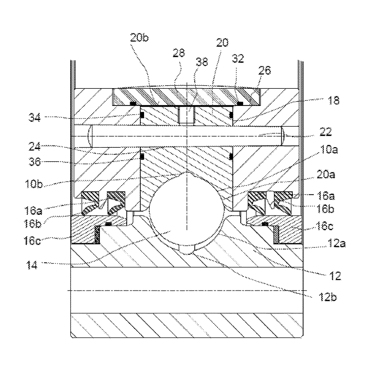
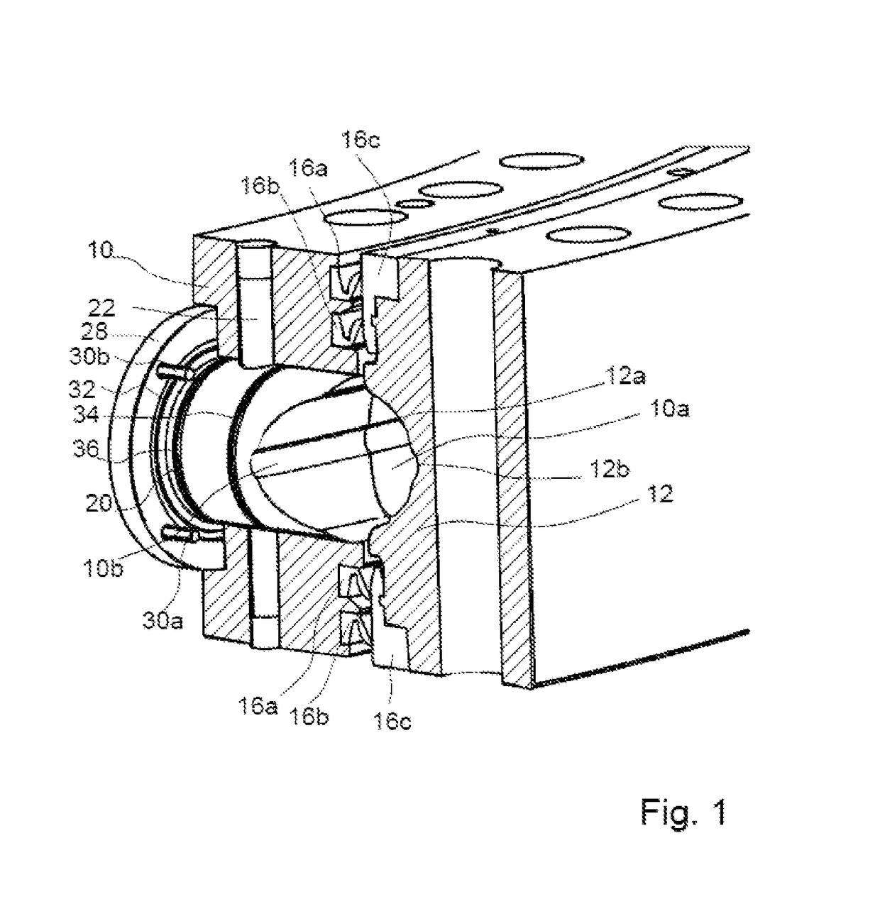
[0010]It is proposed that the plug assembly further comprises a protective cap shielding the outer end face of the plug from a corrosive environment of the bearing. By forming the cap from a material with high corrosion-resistivity a reliable protection of the plug can be achieved and corrosion can be avoided. The mounting and unmounting of the plug remains simple and the watertightness cannot be reduced as a consequence of the corrosion.
[0011]In a preferred embodiment, the protective cap is made of polyetheretherketone (PEEK), which is highly resistant to sea water corrosion, cheap and simple in terms of manufacturing.
[0012]It is further proposed to provide a gasket ring between the protective cap and the surface of the first ring surrounding the opening. The surface of the first ring surrounding the opening is preferably recessed such that that the protective cap can be formed in a flush countersunk manner. The gasket ring avoids sea water leaking in laterally from the edges of the protective cap.
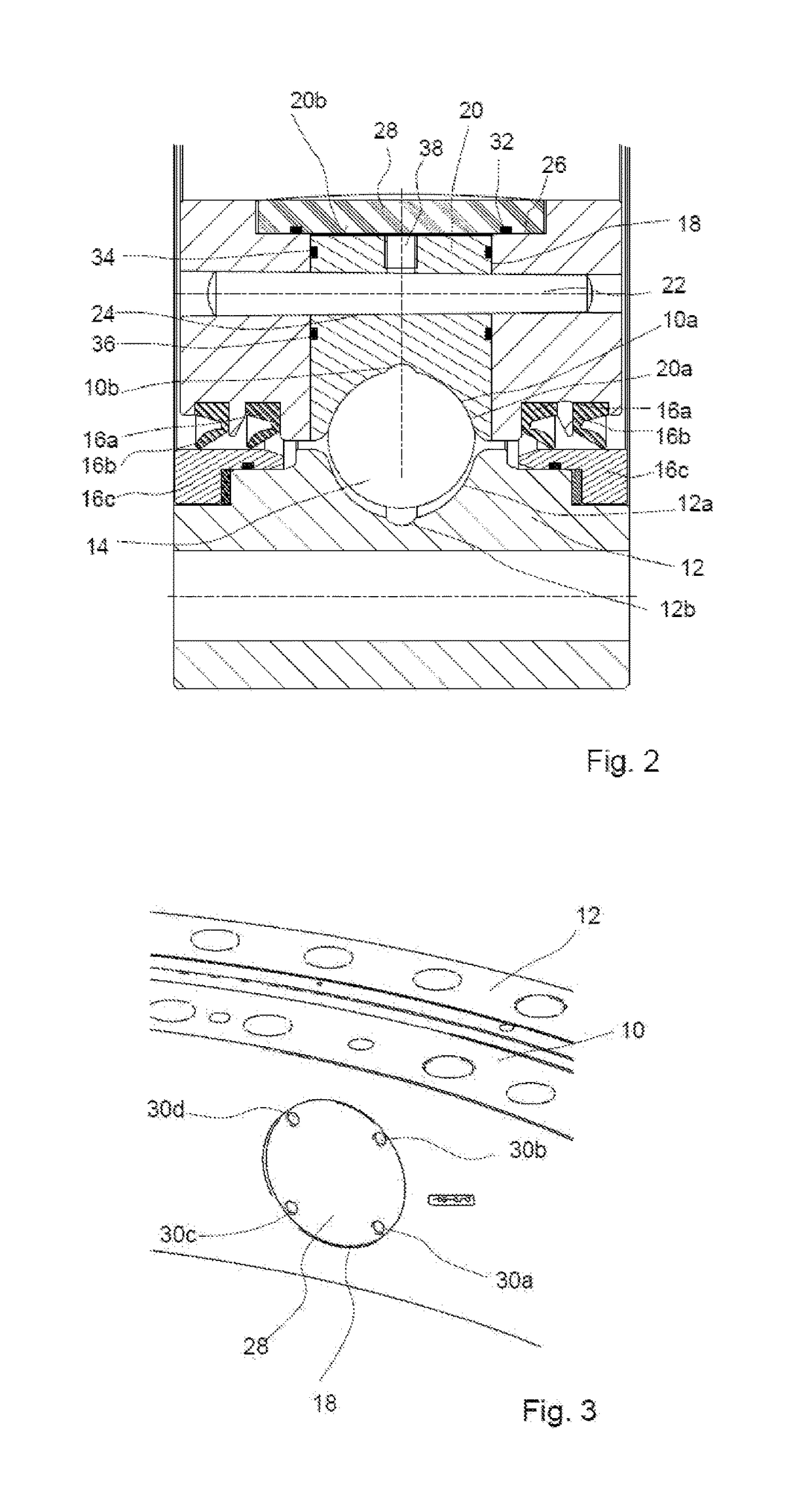
[0013]In a preferred embodiment of the invention, the protective cap is fixed by stainless steel bolts on a surface of the first ring surrounding the opening. The steel bolts are cheap in price, easy to fasten and unfastened and highly resistant to corrosion.
[0015]Further, it is proposed that the plug has an essentially cylindrical outer surface provided with at least one circumferential groove for receiving an O-ring in order to further increase the liquid-tightness of the plug.

Problems solved by technology

The mounting and unmounting of the plug remains simple and the watertightness cannot be reduced as a consequence of the corrosion.

Method used


Image

  • Plug assembly, rolling bearing comprising such plug assembly and machine comprising such rolling bearing
  • Plug assembly, rolling bearing comprising such plug assembly and machine comprising such rolling bearing
  • Plug assembly, rolling bearing comprising such plug assembly and machine comprising such rolling bearing

Examples


Embodiment Construction

[0022]FIG. 1 is a partial section of a rolling bearing according to the invention. The rolling bearing includes a first ring 10 formed as an inner ring and a second ring 12 formed as an outer ring. The rolling bearing is a deep-grooved ball bearing (DGBB) with large diameter and each of the rings 10, 12 is provided with deep grooves forming a raceways 10a, 12a for rolling elements 14 such as balls (FIGS. 2 and 3). A lubricant groove 10b, 12b is formed in the bottom of each raceway 10a, 12a respectively.

[0023]The toroidal space between the raceways is sealed in both axial directions by suitable sealing rings 16a, 16b collaborating with a ring-shaped insert 16c forming a gliding surface on which the sealing ring 16a, 16b abut respectively.

[0024]The first ring 10 is provided with a bore from the radially inner surface of the first ring 10 to the space between the raceways 10a, 10b. The bore is an opening 18 for inserting the rolling elements 14 and suitable spacers (not illustrated) fo...


PUM

PropertyMeasurementUnit
axial lengthaaaaaaaaaa
diametersaaaaaaaaaa
corrosionaaaaaaaaaa

Abstract

A plug assembly for use in a rolling bearing comprising at least a first ring, at least one second ring, and at least one row of rolling elements arranged between the rings. The first ring is provided with an opening for inserting rolling elements into a space between raceways or for taking rolling elements out of the space between the raceways for assembly and maintenance. The plug assembly comprises a plug configured to close the opening when the bearing is operating. The plug includes an inner end face facing the rolling elements and an outer end face opposite to the inner end face. The bearing can further comprise a protective cap shielding the outer end face of the plug from a corrosive environment of the bearing.

Description

CROSS REFERENCE TO RELATED APPLICATION[0001]This is a Non-Provisional Patent Application, filed under the Paris Convention, claiming the benefit of Europe (EP) Patent Application Number 14306521.7, filed on 29 Sep. 2014 (29.09.2014), which is incorporated herein by reference in its entirety.FIELD OF THE INVENTION[0002]The invention relates to rolling bearings, in particular to slewing bearings for submarine applications.BACKGROUND OF THE INVENTION[0003]It is known to provide large-sized rolling bearings, in particular angular contact rolling bearings formed as slewing bearings with large diameters e.g. for wind turbine applications or applications in construction machinery, with an opening for inserting or removing rolling elements upon assembly or for maintenance works.[0004]In angular contact rolling bearing including an opening and a plug for closing the opening is disclosed e.g. in the document WO 2012 / 126529.[0005]In recent times, there is an increasing request for large-sized ...

Claims


Application Information

Patent Timeline
Patent Type & Authority Patents(United States)
IPC IPC(8): F16C19/26F16C43/06F16B37/14F16C19/16
CPCF16C43/06F16C19/26F16B37/14F16C19/16F16C2208/36F16C2360/31F16C2300/14
Inventor BREDOIRE, VINCENTCHAUMONT, NICOLASNICOLAS, MICHEL
Owner AB SKF
Learn More