
Plug connector with improved insulative housing for retaining terminals

a technology of retaining terminals and plug connectors, which is applied in the direction of coupling devices, two-part coupling devices, electrical equipment, etc., can solve problems affecting their proper functioning

Active Publication Date: 2017-04-25
HON HAI PRECISION IND CO LTD
View PDF14 Cites 0 Cited by
  • Summary
  • Abstract
  • Description
  • Claims
  • Application Information

AI Technical Summary

Benefits of technology

[0002]The present invention relates to an electrical connector, and more particularly to a plug connector capable transmitting high frequency signals and stably retaining soldering terminals thereof.

Problems solved by technology

Because there is not any restriction for preventing the soldering portions from moving backwards or upwards, the terminals may move backwards or upwards to thus undesirably affect their proper functioning.

Method used


Image

  • Plug connector with improved insulative housing for retaining terminals
  • Plug connector with improved insulative housing for retaining terminals
  • Plug connector with improved insulative housing for retaining terminals

Examples


Embodiment Construction

[0017]Reference will now be made in detail to the preferred embodiment of the present invention.

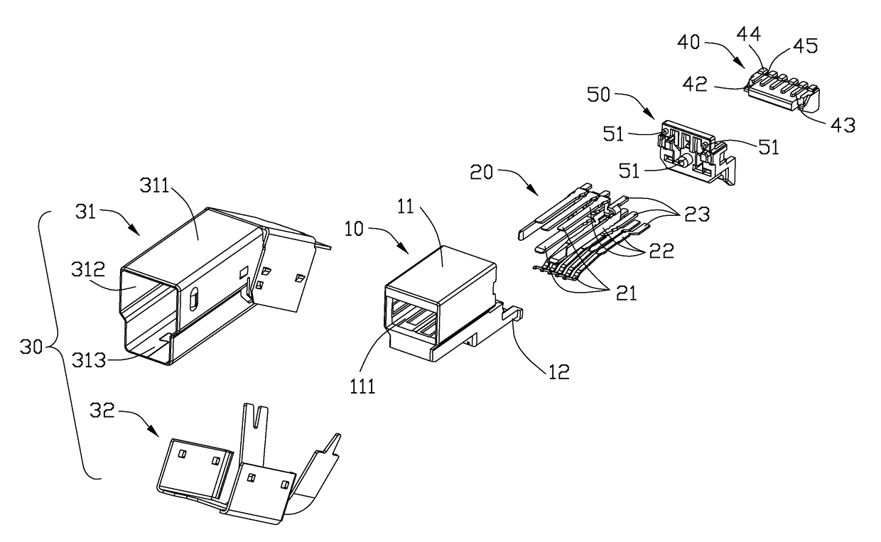
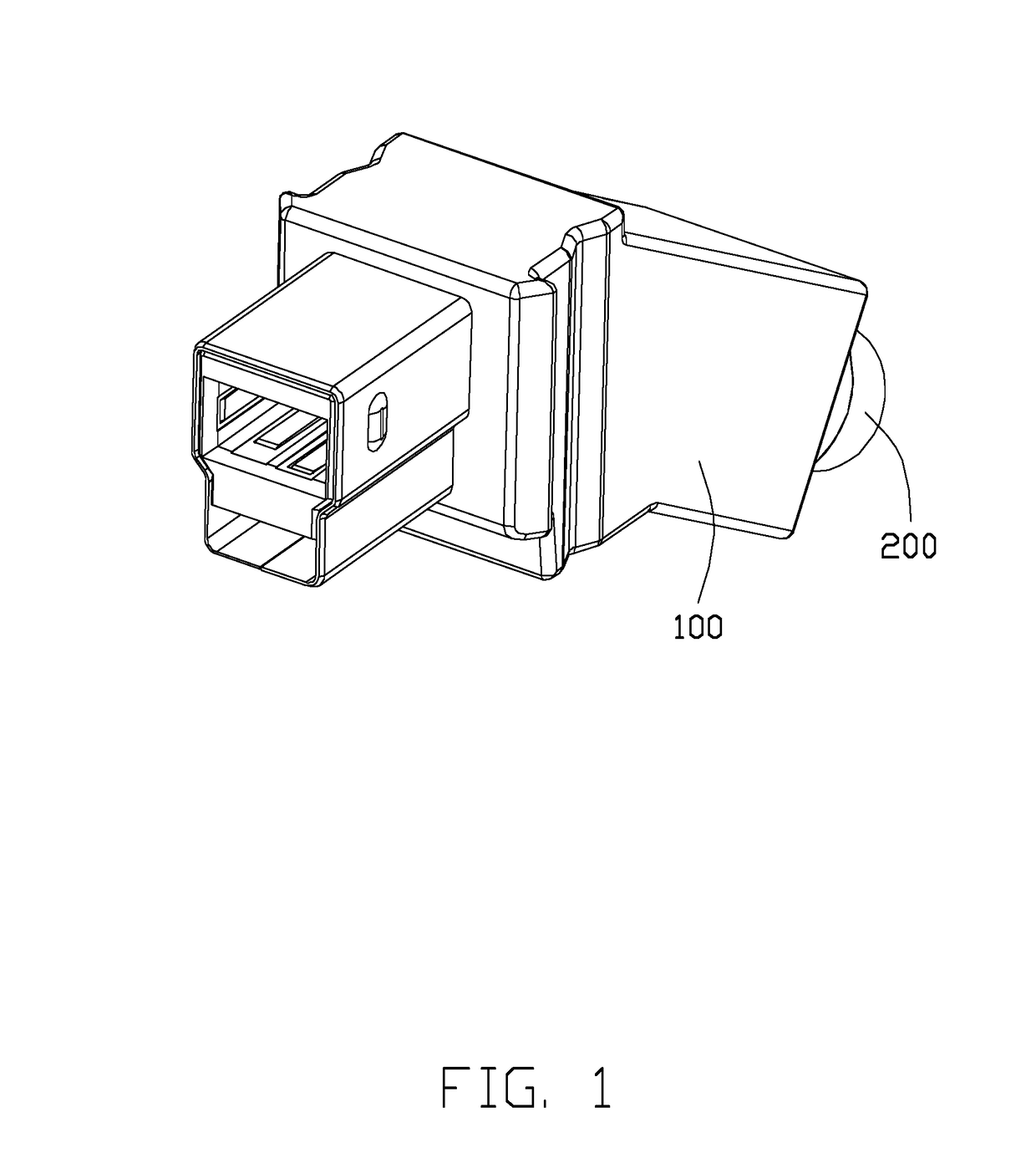
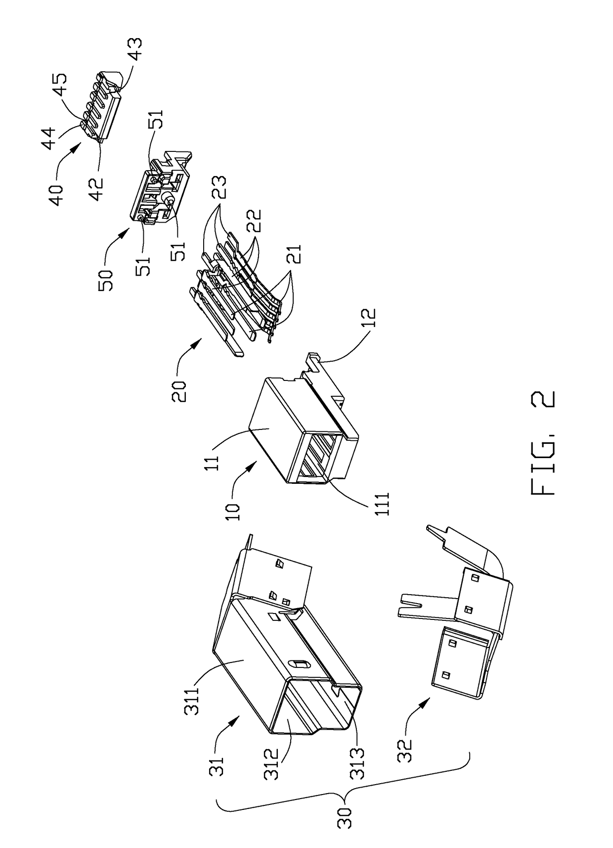
[0018]Referring to FIGS. 1-7, a plug connector 100 in accordance with the present invention connected with a cable 200 is shown. The plug connector 100 may comply with Universal Serial Bus (USB) 3.0 and 2.0 transmission protocols and may be a B-type USB 3.0 plug. The plug connector 100 includes an insulative housing 10, a plurality of terminals 20, an insulative block or lower spacer 40, an insulative body or upper spacer 50, and a shielding shell 30. The terminals 20 are retained in the insulative housing 10 for transmitting USB signals. The shielding shell 30 covers the insulative housing 10, the insulative block 40, and insulative body 50.

[0019]The insulative housing 10 includes a main portion 11, an extending portion 12, a receiving chamber 111, and at least one dovetail groove 121. The extending portion 12 extends backwards from a lower section of the main portion 11. The receiving c...


PUM


Abstract

An electrical connector includes an insulative housing defining a chamber, a number of terminals mounted in the insulative housing, and an insulative block mounted to the insulative housing. Each terminal includes a mounting section mounted in the insulative housing, a contacting section protruding forwards from the mounting portion, and a soldering section protruding backwards from the mounting portion. The contacting sections are exposed to the chamber. The insulative block has a number of guiding ribs and a number of stopping ribs located behind the guiding ribs respectively. Two adjacent guiding ribs define a receiving slot for receiving the soldering section. The stopping rib has a top blocking section.

Description

BACKGROUND OF THE INVENTION[0001]1. Field of the Invention[0002]The present invention relates to an electrical connector, and more particularly to a plug connector capable transmitting high frequency signals and stably retaining soldering terminals thereof.[0003]2. Description of Related Art[0004]U.S. Pat. No. 8,011,968, issued on Sep. 6, 2011, discloses an electrical connector including an insulative housing extending along a front-to-back direction, a set of terminals retained in the insulative housing, and a metal shell enclosing the insulative housing. Each terminal includes a mounting portion retained in the insulative housing, a contacting portion continuing forwardly from the mounting portion for connecting with a mating connector, and a soldering portion protruding backwardly from the mounting portion for soldering with a corresponding wire of a cable. The insulative housing has a row of guiding ribs defining a row of receiving slots between every two adjacent guiding ribs. ...

Claims


Application Information

Patent Timeline
Patent Type & Authority Patents(United States)
IPC IPC(8): H01R13/506H01R13/436H01R12/71H01R24/62H01R13/6581
CPCH01R13/506H01R13/4367H01R12/716H01R13/6581H01R24/62H01R13/426
Inventor WU, JERRYCHEN, JUNFAN, XIAOZHOU, ZHI-YONG
Owner HON HAI PRECISION IND CO LTD
Learn More