
Wellbore pressure control system and method for offshore well cementation stages

a wellbore pressure control and wellbore technology, applied in the field of offshore oil and gas exploitation, can solve the problems of long-section leaky zone and multi-layer leaky zone, posed a serious challenge to deep water well cementation technology, and cannot be overcom

Active Publication Date: 2017-04-25
CHINA UNIV OF PETROLEUM (EAST CHINA)
View PDF9 Cites 6 Cited by
  • Summary
  • Abstract
  • Description
  • Claims
  • Application Information

AI Technical Summary

Benefits of technology

The present invention provides a system and method for controlling wellbore pressure during cementation stages. It prevents the formation from fracturing and avoids safety accidents such as well kick and well blowout. This is achieved by utilizing a return pipeline to decrease the pressure on leaky zones in the wellbore by injecting a low-density fluid or gas. After packing up long-section and multi-formation leaky zones, the well cementation is continued in the upper ordinary formation. The technical scheme effectively prevents wellbore pressure control issues during cementation stages.

Problems solved by technology

Deep water well cementation is an indispensable step in the oil and gas development process in the deep sea areas, but the difficulties brought by deep water has posed a serious challenge to deep water well cementation technology.
For deep water formation with a narrow safety density window, applying the traditional well cementation method can let the high-density cement slurry fracture the formation that further cause safety accidents such as well kick and well blowout, etc.
However, during deep-water well drilling, challenges from long-section leaky zones and multi-layer leaky zones, etc., are often encountered, and can't be successfully overcome with the above-mentioned well cementation techniques.
Usually, to overcome such challenges, three stages, four stages or even more stages of well cementation are required; consequently, the well drilling difficulty is highly increased, and the drilling efficiency is severely decreased.

Method used


Image

  • Wellbore pressure control system and method for offshore well cementation stages
  • Wellbore pressure control system and method for offshore well cementation stages
  • Wellbore pressure control system and method for offshore well cementation stages

Examples


Embodiment Construction

[0030]Hereunder some embodiments of the present invention will be detailed with reference to the accompanying drawings. It should be appreciated that the embodiments described here are only provided to describe and explain the present invention, but shall not be deemed as constituting any limitation to the present invention.

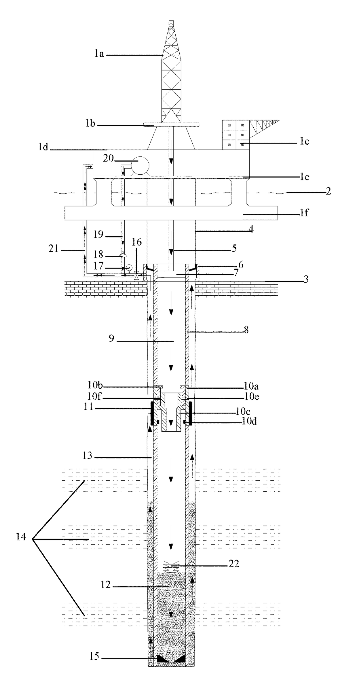
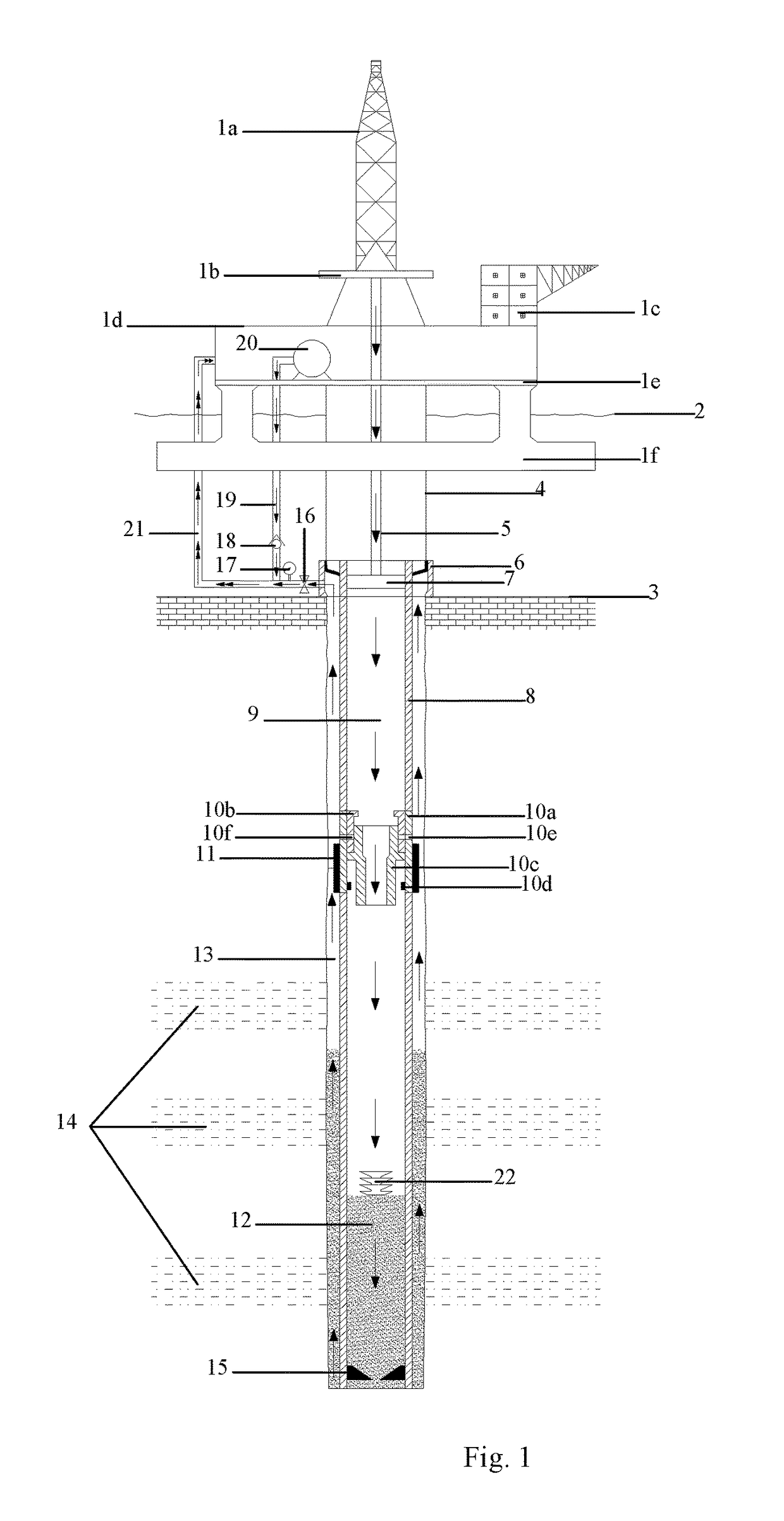
[0031]To overcome the challenge from long-section leaky zones and multi-formation leaky zones in deep-water well drilling, the present invention provides a wellbore pressure control system, which utilizes a return pipeline to lift the fluid in an annular space in the wellbore back to the platform, while injecting a low-density fluid or gas into the return pipeline to decrease the pressure of liquid column in the return pipeline and thereby decrease the pressure acted on the leaky zones in the annular space of the wellbore. After long-section leaky zones and multi-formation leaky-zones are packed up, the external casing packer is opened to separate the long-sectio...


PUM


Abstract

The present invention provides wellbore pressure control system and method for well cementation stages, and relates to the offshore oil and gas exploitation field. The wellbore pressure control system comprises: an injection pump; and a control device, configured to control the injection pump to inject a fluid or gas through an injection pipeline to a return pipeline that communicates with an annular space of the wellbore to decrease the pressure in the return pipeline and thereby decrease the pressure in the annular space, wherein, the density of the fluid or gas is lower than the density of a drilling fluid in the annular space. The technical scheme of the present invention can effectively prevent leaky zones from being fractured by high-density cement slurry in the well cementation process that may cause safety accidents such as well kick and well blowout, etc.

Description

CROSS REFERENCE TO RELATED APPLICATIONS[0001]This application claims priority to Chinese Application No. 201610806790.1, filed on Sep. 7, 2016, entitled “Well Bore Pressure Control System and Method for Offshore Well Cementation Stages”, which is specifically and entirely incorporated by reference.FIELD OF THE INVENTION[0002]The present invention relates to the offshore oil and gas exploitation field, and particularly relates to a wellbore pressure control system and a wellbore pressure control method for well cementation stages.BACKGROUND OF THE INVENTION[0003]Deep sea areas are abundant in oil and gas resources, and it is an irresistible trend to further exploit and utilize the oil and gas resources in the deep sea areas. Deep water well cementation is an indispensable step in the oil and gas development process in the deep sea areas, but the difficulties brought by deep water has posed a serious challenge to deep water well cementation technology. Owing to the fact that certain p...

Claims


Application Information

Patent Timeline
IPC IPC(8): E21B33/14E21B43/12E21B33/12
CPCE21B33/146E21B43/12E21B33/12E21B33/13E21B33/138E21B47/06
Inventor SUN, BAOJIANGWANG, XUERUIMA, YINGWENGAO, YONGHAI
Owner CHINA UNIV OF PETROLEUM (EAST CHINA)
Learn More